Radio frequency (far field) field strength measurements are taken with dedicated instruments composed by a calibrated receiving antenna and a calibrated instrumentation receiver. Basically, any antenna connected to any receiver capable of measuring the signal strength can be used for the same purpose, but with less precision. This page explains how to find the field strength at a given point, given the received power and the gain of the antenna.
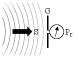
The following diagram summarizes the situation: a radio wave of power density S travels into space and finds a receiving antenna of gain G that picks up some of the wave energy and gives it to a receiver that measures it as Pr.
This measurement must be done in the far field region, otherwise the formula used here are not valid. This means that the measurement must be taken at an adequate minimum distance from the transmitter that generated the wave, so that we can neglect it and suppose that we have a nice and spherical wave. This is not a big limitation, since antennas are normally intended to be used far away from each other.
Each antenna has its own equivalent area Ae describing its ability to "collect" the power of an incoming wave. Somehow, if you have a power density S of, say, 1 mW/m2 and an antenna picks up 2 mW of power, it's like if it harvested the power on an area of 2 m2. This is the antenna equivalent area Ae; it's a virtual surface that does not correspond to the physical antenna surface (except, maybe, parabolic reflectors antennas). It's independent on the type of the antenna; it only depends on its gain g and the working wavelength λ:

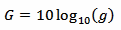
Here we need the gain g in terms of power ratio, so the usual gain G in dB must be converted first with:
By definition, the gain takes into account the directivity of the antenna and its losses. If significant, any additional loss introduced by the cable or any other device between the antenna and the receiver, can be included by reducing G accordingly.
Wavelength λ and frequency f are related by the following equation:

Where c0 is the speed of light. For vacuum (and air), c0 = 299'792'458 m/s.
Knowing the equivalent area Ae and the received power Pr of an antenna, we can calculate the power density of the incoming wave with the following equation:

Now, the strength of an electromagnetic wave can be expressed in terms of electric field strength E (measured in V/m), of magnetic field strength H (measured in A/m) or of power density S (measured in W/m2). The most common is the electric field strength, but in the far field region, they are all equivalent and related by the following two equations:
 and
and
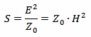
Where Z0 is the characteristic impedance of vacuum that is Z0 = 120π Ω ≈ 377 Ω
So, we can easily convert S into E and H.
Please remark that this is only valid if all the following conditions are met:
Enter the frequency f, the gain G and one value (either pr, Pr, E, H or S) and click the "Convert" button next to it to compute the other values.
You can also use this calculator to convert only between E, H and S: in this case, just enter any valid value for f and G.
A mobile phone contains an antenna and a receiver capable of measuring the received signal strength. Usually, the signal strength is only displayed with a few "bars" or "bricks" next to an antenna logo. But on many models, with an additional network monitor application, true measurements can be obtained, and the field strength can be calculate with a reasonable accuracy.
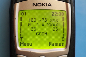
For example, this mobile phone is receiving GSM channel (also called ARFCN) number 103 with a signal strength of –76 dBm (first two numbers of the first row). According to the GSM standard, channel 103 corresponds to a downlink (network to mobile) frequency of 955.600 MHz. The exact gain of the mobile phone internal antenna is not known, but assuming 0 dBi is probably a good guess.
With this information, we can calculate the electric field strength E = 1.1 mV/m, the magnetic field strength H = 2.9 μA/m and the power density S = 3.2 nW/m2.
If we wanted to know what is the received power by this same mobile phone when the electric field strength is, say, 1 V/m, we can use the calculator in the other way and we get Pr = –17 dBm.
Now, this is probably too much to be reliably measured by a mobile phone: the model in the picture gives good results between –100 and –60 dBm, which is the usual GSM signal range; stronger signals saturate the receiver and give inaccurate (underestimated) figures. Other models may have a different behavior. Since a mobile phone is not a watt-meter, some testing with known signals is required before trusting its readings.
| [1] | C.-A. Balanis. Antenna theory, analysis and design. Wiley, 1997, Chapter 2. |
| [2] | P.-G. Fontolliet. Traité d'Électricité, Vol. XVIII: Systèmes de télécommunications. Presses Polytechniques et Universitaires Romandes, 1996, Section 3.9. |
| [3] | X. Lagrange, P. Godlewski, S. Tabbane. Réseaux GSM-DCS. 4ème édition. Hermes Science Publications, 1999, Chapitres 6 et 7. |
| Home | Electronics | Index | Page hits: 136162 | Created: 09.2000 | Last update: 11.2012 |