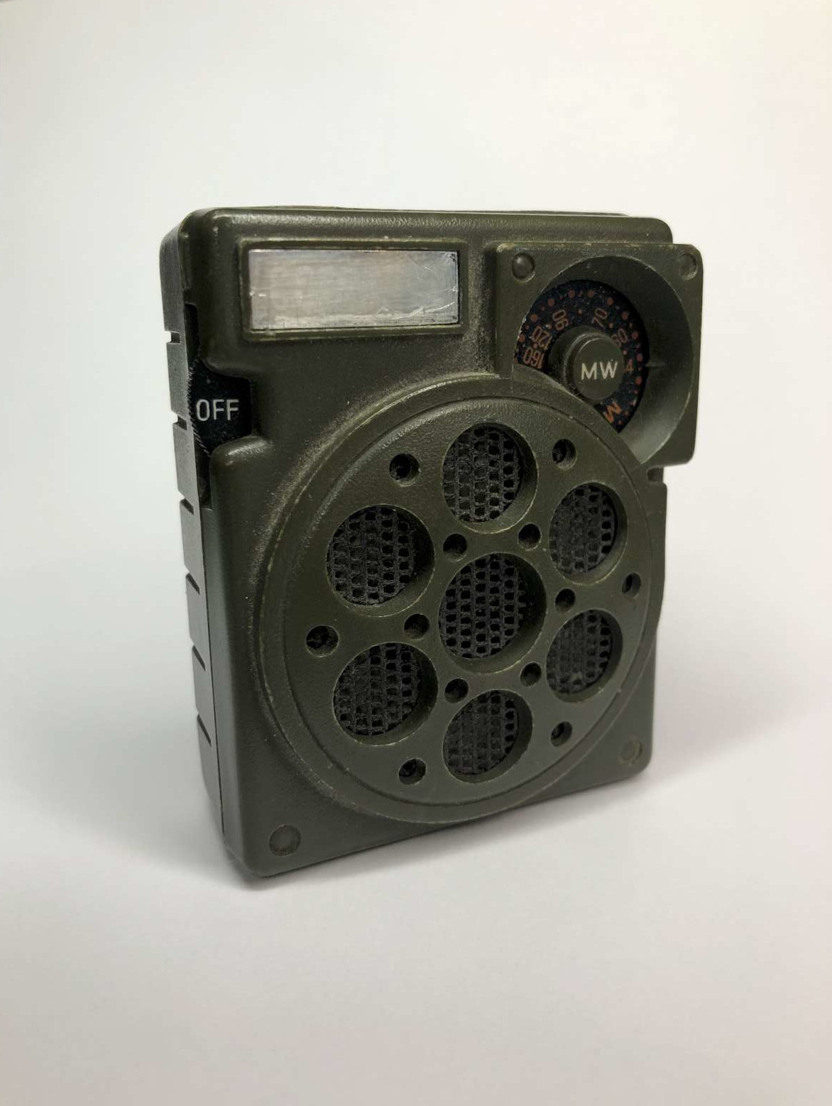
Exterior view before the restauration. (click to enlarge)
A few months ago, while looking for something else, I found in a drawer an old AM transistor radio receiver I loved when I was a kid. It was given to me at the beginning of the 1980s by my grandfather. It was really small for the era, smaller than a cigarette pack. It has a speaker, a tuning control, a volume control, and runs with a single AA cell. It tunes the MW (medium waves) band from about 530 to 1'700 kHz. Being a kid I really loved that radio and brought it with me everywhere. And I still find it cute today. In the daytime I could listen to the local station and to a very powerful Italian station about 80 km away. At night it would pick much more stations all around Europe. This was in the eighties; today unfortunately all the local stations have gone off the air and listening to the AM band is only possible at night.
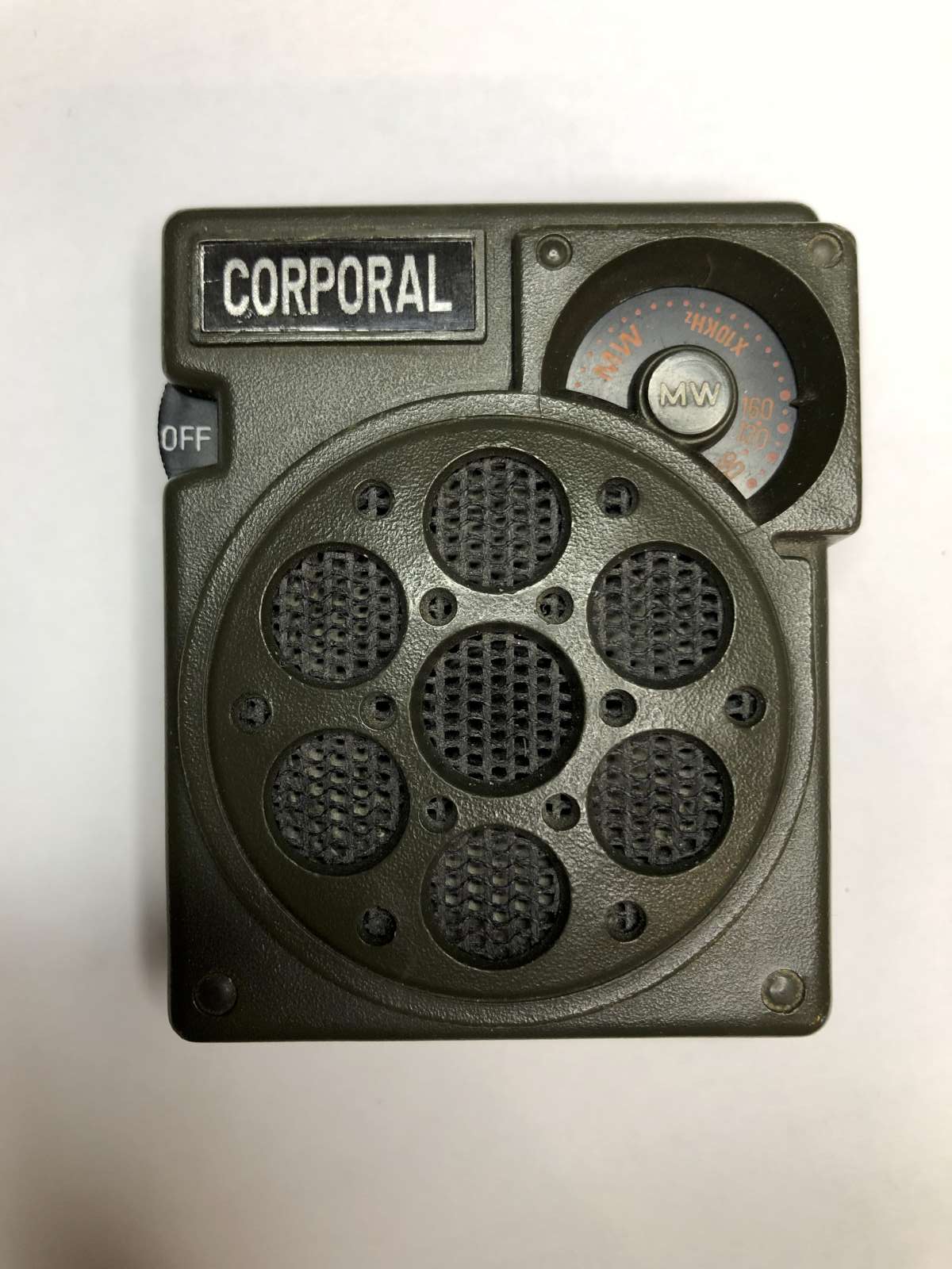
Exterior view before the restauration. (click to enlarge)
It has no brand, or more precisely, not one that I know of. It has a military-like look and a camouflage green color, but it's not a military radio: it's made of plastic and it's not as rugged as true military equipment. A label on the front face used to say "CORPORAL" but it was completely faded away. My grandfather said he bought it in an outlet in Livorno, Italy, in the late sixties or the early seventies, but I'm not sure about the date. I wish he was still around to ask more information. It's not a particularly good or valuable radio: I just like it.
From what I could find on the internet, the same exact model was branded under different names, like "TAMMY", "VEM", "BRONCO" and of course "CORPORAL", but I wasn't able to find who produced it and when. From the components it has it could have been manufactured in Hong Kong, and the design matches the design of the early seventies, but I'm not sure.
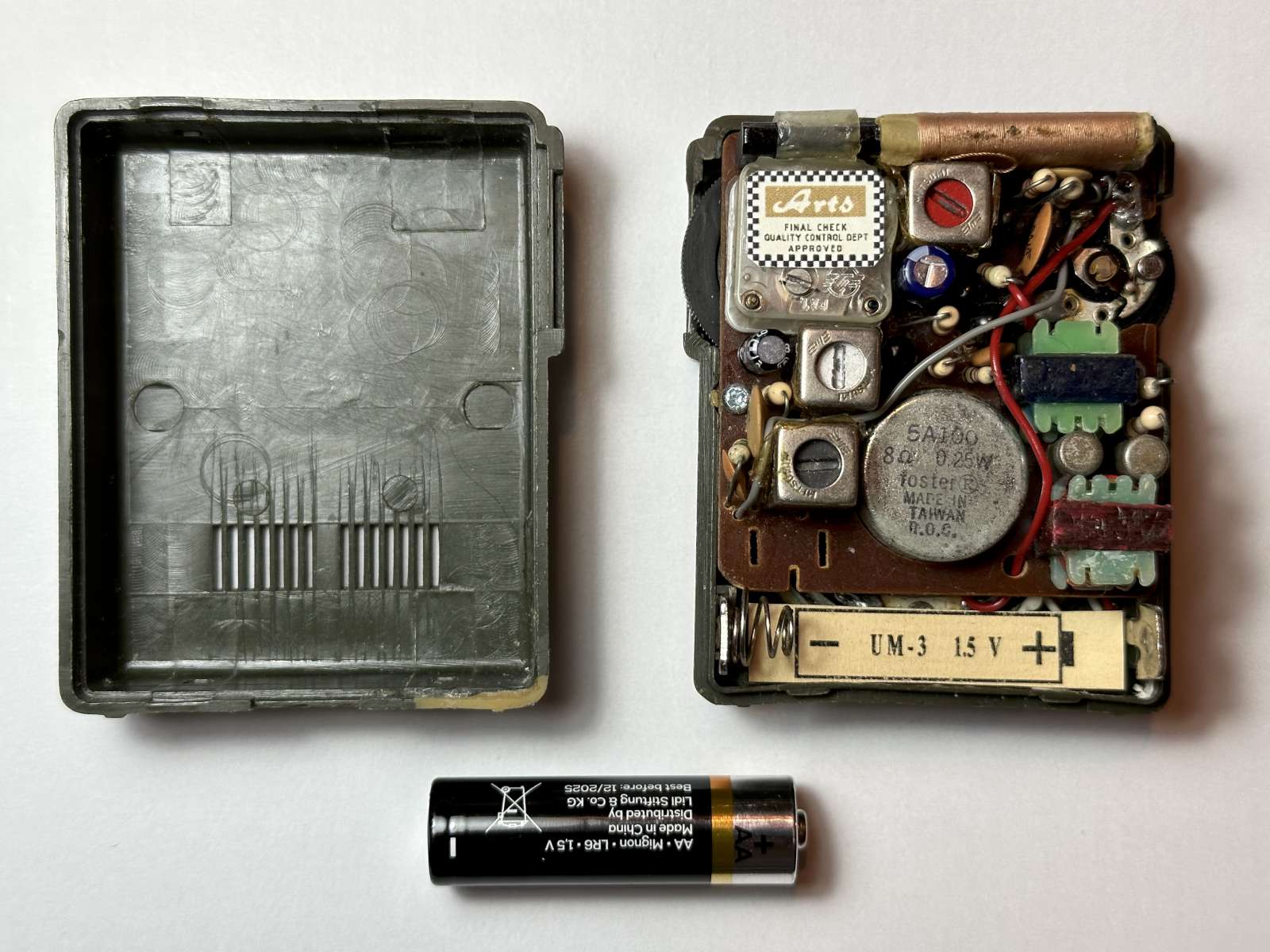
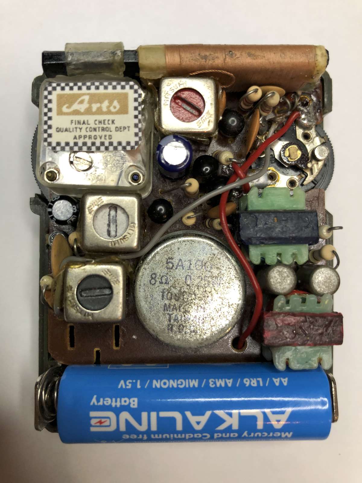
I was always amazed how this radio could work with just a single 1.5 V AA cell. All other radios of the same era had at least two cells, at least 3 V, but 9 V batteries were much more common. It was constructed way before DC-DC converters went in fashion and the whole analog circuit runs directly from the battery with just 1.5 V. It has 6 transistors, one local oscillator transformer, two intermediate frequency (IF) transformers (most AM radio have three) and two audio transformers. At first glance it looks like a classic super-heterodyne receiver, and it is. But I always wondered how it could work with such a low voltage.
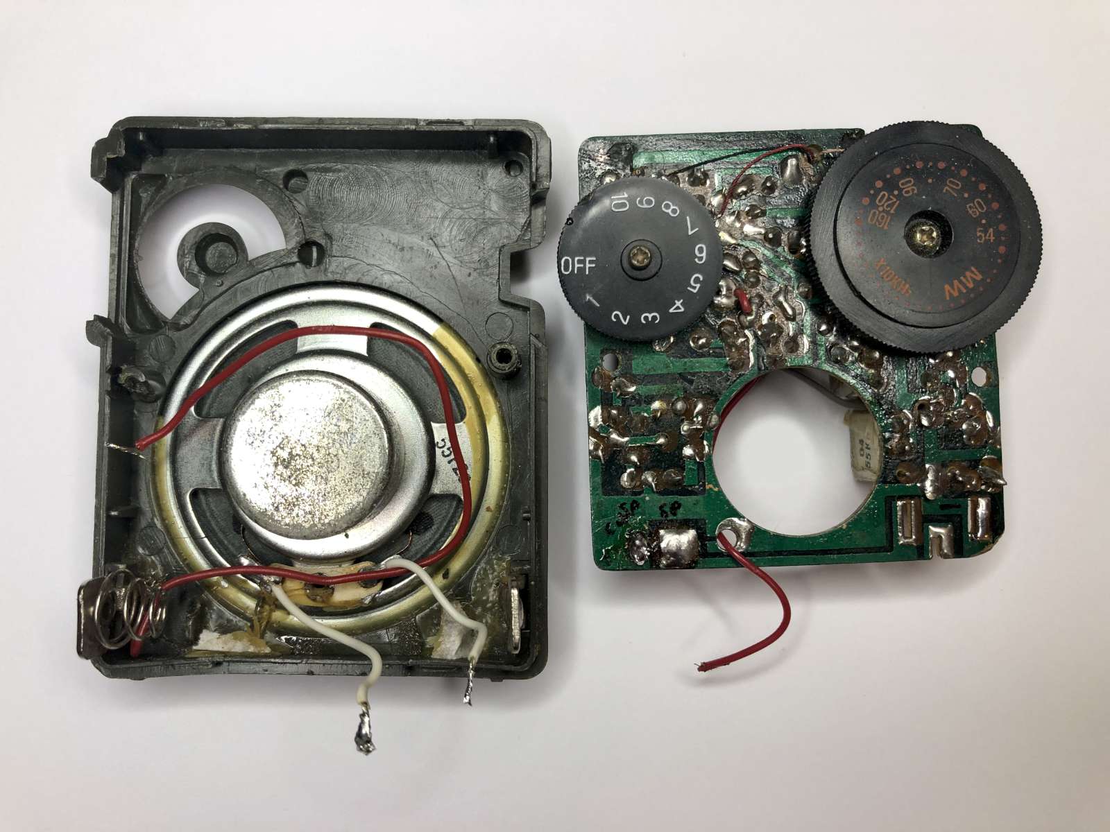
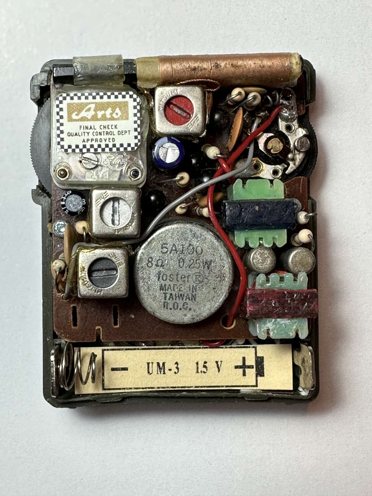
I always wanted to take it apart to understand how it works, to study it schematic. I'm glad I didn't do it back then: my 8 years old me would certainly have destroyed it in such an attempt. All components are so packed together that the reverse engineering is a challenge, even today. It's from an era before SMD components: all parts have leads and are mounted as close to each other as possible. The PCB is made of Bakelite and is single sided. Only one wire connects to distant points of the board and all the other connections are on the bottom side of the PCB. A lot of thoughts went into the layout and the routing, that's sure. The traces are hand drawn. Components don't have regular patterns and sometimes "step on their neighbors toes", so to speak.
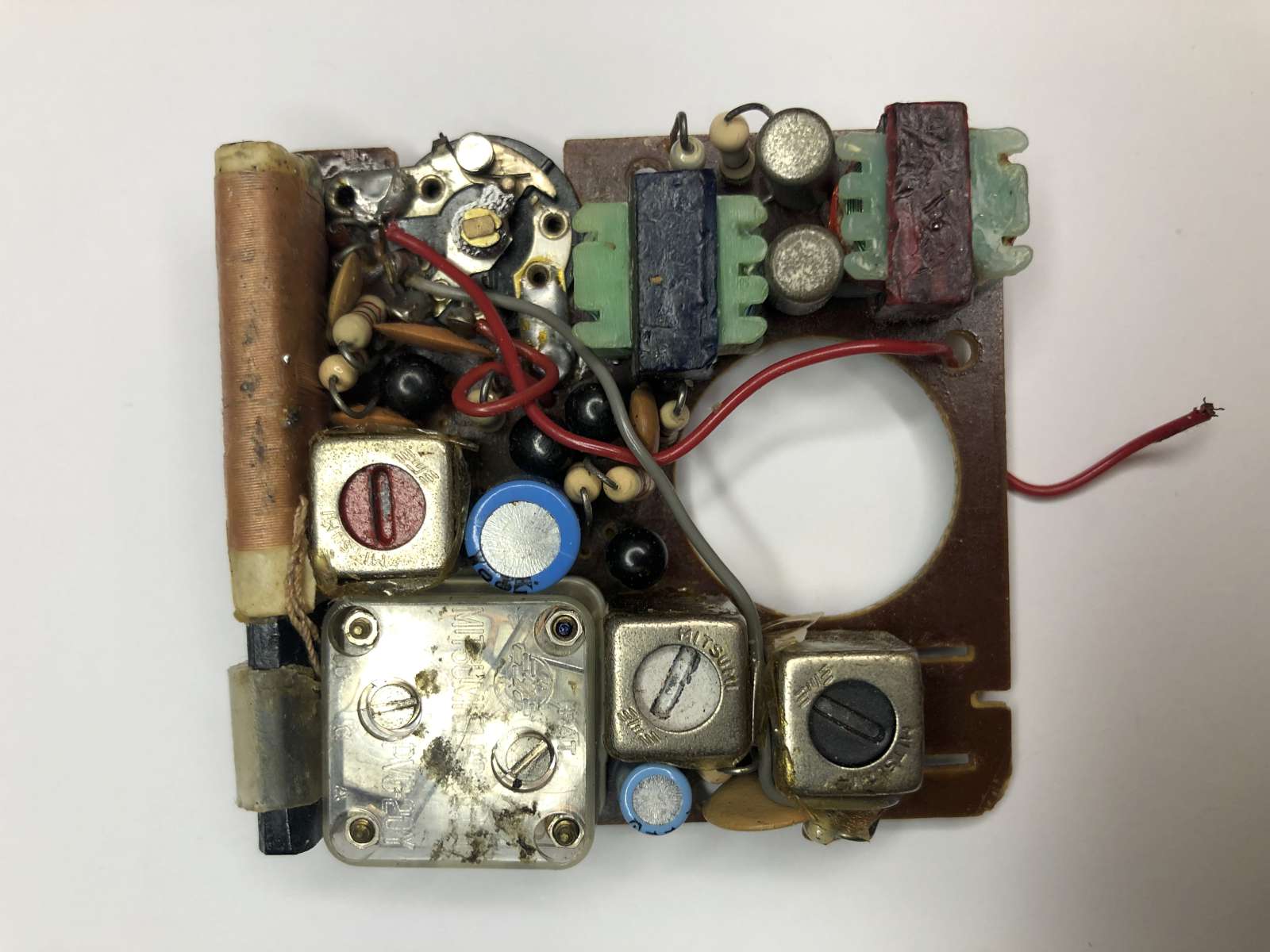
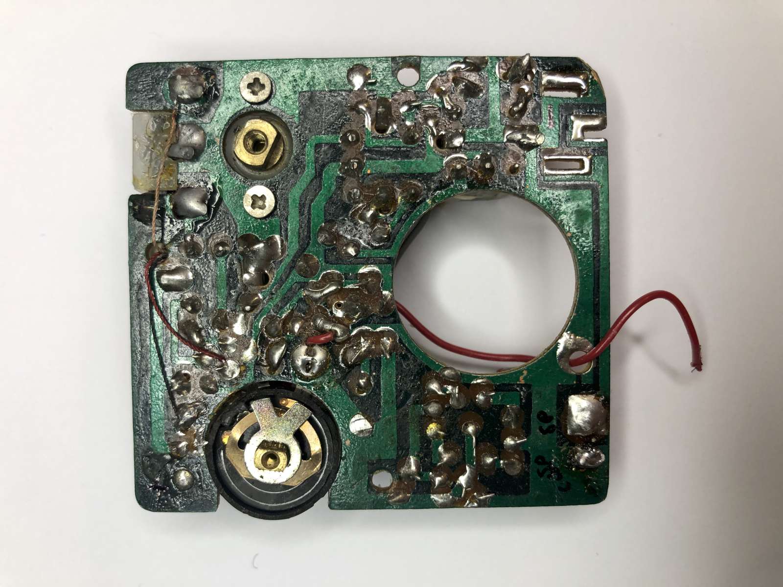
View of the PCB before the restauration. (click to enlarge)
The first thing I wanted to know is if it still worked. I installed a fresh AA cell and switched it on: it did. That's impressive: after 50 years or so, it still works. Wow! It could tune a few stations, but the audio was not very good. So I checked the two electrolytic capacitors and sure enough one was still acceptable but the other one was dry. Not a problem, I replaced both to be on the safe side and it was as good as new.
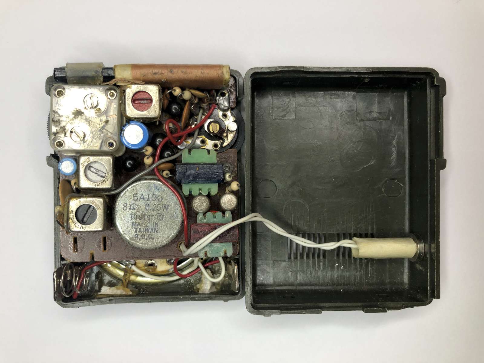
Inside view before the restauration. (click to enlarge)
The plastic housing needed some attention, too. When I was a kid I had the idea of installing an earphone socket and I drilled a hole... now I regret it. So I closed it with some epoxy resin and I also reconstructed some broken edges, too. The radio had a wrist strap, but the hook is broken and there is no way I could restore it, so it has to stay without it. I decided not to paint the housing and leave the resin repairs visible to remind the story of this radio and that it survived a kid with a passion for electronics...
Inside view of the complete radio after the restauration. (click to enlarge)
The finished radio with a new logo label. (click to enlarge)
It lacked the factory label on the tuning capacitor and another label under the battery to indicate its polarity. I could reconstruct the both of them from two pictures I found on the internet. I have to say the look exactly as I remember them, I was lucky.
Inside view of the restored radio with and without battery. (click to enlarge)
The circuit is not very different form the classic 6-transistor super-heterodyne circuit used in every other radio of the era until analog ICs become popular in the eighties. The first transistor T1 is used as both oscillator and mixer. The oscillator is based on the coupling (positive feedback) provided by the red-core transformer MF1. AM signals are received by the ferrite antenna and the transistor does double duty of oscillating and mixing the received signal. The only unusual part is the base polarization provided by two silicon diodes D1 and D2 in series instead of the more classic resistive voltage divider.
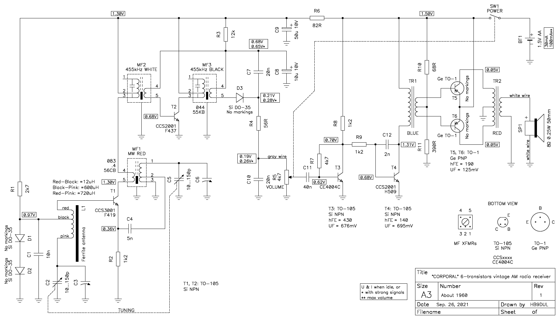
Schematic of this Corporal 6-TR solid state AM receiver. (click to enlarge)
The full schematic is available here: corporal-6-tr-mw-radio-schematic.pdf (48,826 bytes).
Instead of the classic two IF (intermediate frequency) amplifiers and three IF transformers (the usual order is a yellow-, a white- and black-core) this radio has only one IF amplifier transistor (T2) and two IF transformers (a white- and black-core, MF2 and MF3). This is to save space at the expense of a lower selectivity. The IF frequency is the classic 455 kHz, no surprise there. The detector and AGC (automatic gain control) circuit is unusual as the rectifier diode D3 is usually turned in the other way. But as the AGC output is still taken from the diode cathode, the effect is still to lower the base voltage with increasing signal strength obtaining a constant volume regardless of the strength of the received signal.
But the gain of the missing second IF amplifier is compensated by using two AF (audio frequency) amplifier transistors T3 and T4 instead of just one. The final AF amplifier is a classic push-pull amplifier with pilot and final audio transformers, typical of all transistor super-heterodyne circuits of the era.
It's not easy to use bipolar junction transistors with only 1.5 V. Normally for a "class A" amplifier, let's say for an NPN transistor, you want the emitter sitting at a few volts above ground through an emitter resistor to stabilize the temperature coefficient. Than you need the collector to sit at least one junction voltage above the emitter (about 0.7 V for silicon transistors and 0.3 V for germanium). And then you need some headroom between the collector and the positive supply rail to allow for some output amplitude. Or, at least, this is how I was taught to.
The first trick that comes to my mind is to use germanium transistors instead of silicon ones. The lower junction voltage frees about 0.4 V of headroom... but this is not what this radio uses. I surprisingly found that four transistor out of six are silicon ones; only the two final transistors are germanium. The two germanium ones are PNP, they are in TO-1 cases but have no marking on them; they look like AC128 but I don't know what the exact part number is. The four silicon transistors are all NPN in TO-105 cases. They are marked, but I was unable to find any information about them. They are marked "CCS2001", "CCS3001" and "CE4004C", but I have no idea who manufactured them and when.
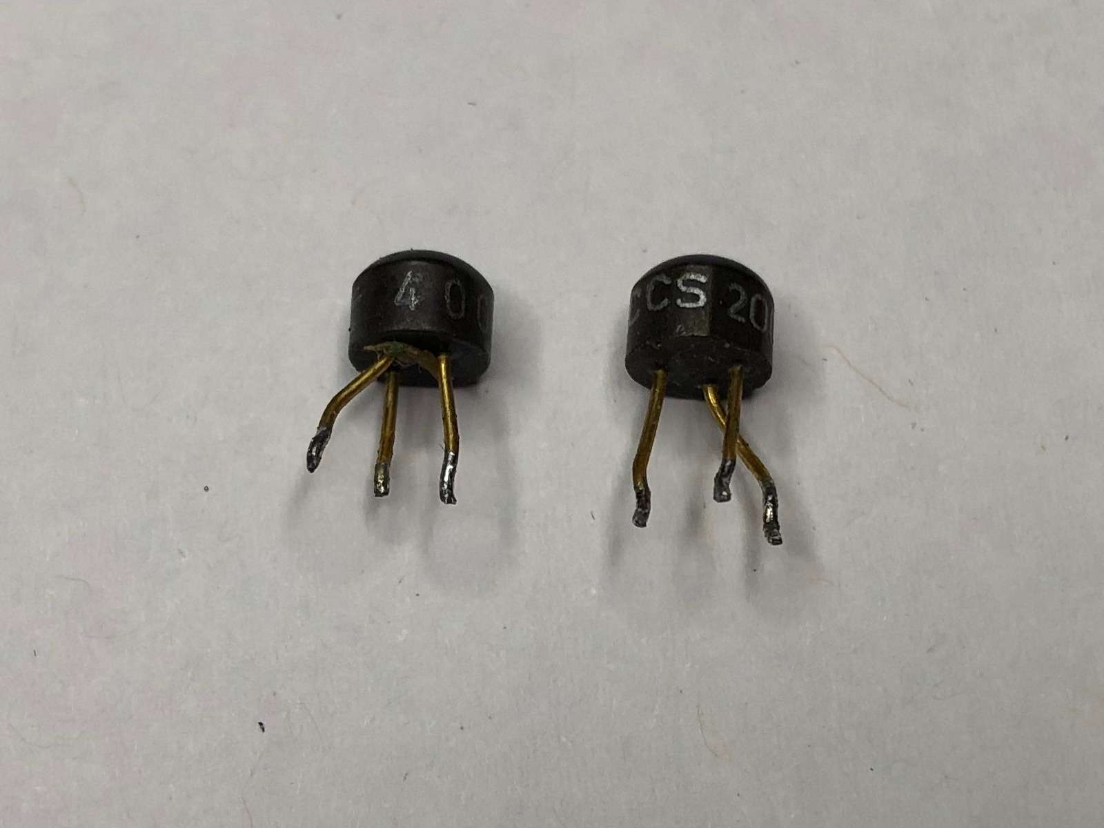
Two of the four silicon transistors. (click to enlarge)
The second trick is to load the collector with a transformer instead of the classic resistor. In this configuration the collector (when idle) sits at the supply voltage and the instantaneous voltage can swing both below and above the idle voltage making more space for the output signal. This trick is used everywhere in this radio: all transistors have a transformer on their collector.
I was taught to never connect the emitter directly to ground to avoid thermal runaway, but here it's exactly what they did. With the exception of the oscillator/converter transistor T1, all the other ones have their emitter directly connected to ground. In this configuration, the transistors are not thermally stable and are at risk of thermal runaway, i.e. if they heat up their gain increases, they turn on a little more and they heat up even more entering a sort of self-destruction mode. Why isn't this a problem in this radio? I don't know, and didn't feel like putting it into an oven after 50 years of good service to test what happens. Here it works, but in theory, you shouldn't design a circuit like that... On the other hand, what can you do with only 1.5 V? The designers probably had no choice. Maybe the internal resistance of the battery somehow limits the current to avoid the worst, but it's just a hypothesis, I didn't test it.
Another surprising fact is that this circuit uses the negative pole of the battery as ground. In radios of this era, the positive is very often used. I know, I should say common instead of ground because this is a portable radio and there is no actual buried underground electrode. But English is not very precise in this respect and the term ground (or earth) is ambiguous at it can mean a direct physical connection to the earth via a buried electrode like for a lightning rod, a common return path for electric current, or simply a reference 0 V point from which voltages are measured. Here, ground means the two latter definitions, but not the first one.
So, after all, it's a cute little radio. I'm happy I could restore it and that after 50 years it's still as good as new. The housing has some scratches and marks that testify its age and the fact that it survived an 8 years old kid with a knack for electronics... It's just a pity that AM radio stations are a thing of the past and there little left to listen in the MW band, at least in central Europe. And if you happen to have the same radio maybe you’d appreciate to find its schematic here.
| Home | Electronics | Page hits: 017277 | Created: 05.2022 | Last update: 05.2023 |