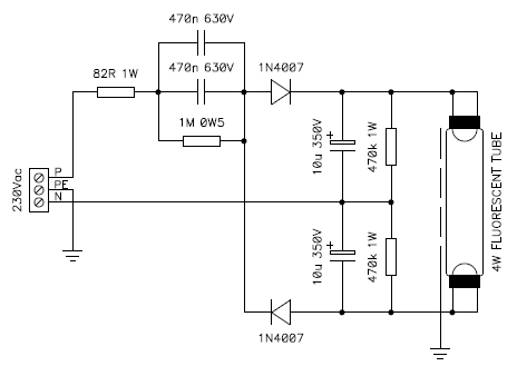
Circuit diagram of the lamp driver.
I present here an unusual circuit to drive a small fluorescent tube with DC. Its use is very limited and definitely not as good as traditional AC "starter and ballast" circuits, but for didactic purposes I still find it interesting as an alternative and uncommon way of connecting these lamps.
Fluorescent tubes are built by two electrodes in a low pressure atmosphere composed by a mixture of gasses; usually argon and mercury vapor. When the tube is off it behaves like an insulator until the voltage between its electrodes rises above a threshold called striking voltage (or starting voltage or ionizing voltage). The actual value depends on many factors, like gas composition, gas pressure, electrode material, electrode temperature and so on. Without preheating the electrodes, it can be as low as a few hundred volts for small tubes and as high as several tens of kilovolts for long tubes. Normally, the electrodes are preheated to reduce the starting voltage by about a factor of ten, but this is not what is done here.
When the starting voltage is reached, the gas ionizes, a current start flowing and light is produced. The voltage between the electrodes falls to a low value, somewhere between 30 and 100 V, depending on the tube length and on the composition of the gas inside. The current must be limited by a ballast circuit to keep the lamp at its nominal power rating and prevent it from overloading.
Circuit diagram of the lamp driver.
Fluorescent tubes are almost always powered with AC, but this circuit uses DC. Basically, this circuit is a voltage doubler composed by two 1N4007 diodes and two high voltage electrolytic capacitors of 10 μF 350 V. Such capacitors can be easily salvaged from compact fluorescent lamps.
When the tube is off, the diodes rectify and double the 230 VAC mains producing about 650 VDC at the electrodes of the lamp. This voltage is high enough to directly start a low power fluorescent tube without preheating the electrodes. It works fine with 4 W tubes and with many 8 W ones, but 12 W tubes are tricky and don't always start reliably. I tried to connect both terminals of each electrode together or only one per electrode with no noticeable difference.
Even if I didn't try, I doubt that this circuit will work with 120 VAC mains, as a simple doubler is probably not enough to generate the high voltage to strike the tube.
Once the tube is lit and the current starts flowing, the two 470 nF capacitors act as ballast: they limit the current and drop the voltage so that the tube can operate safely. When on, the voltage between the electrodes of a 4 W tube is about 30 V. Why two 470 nF capacitors in parallel? Just because I didn't have any 1 μF on hand.
The 1 MΩ resistor and the two 470 kΩ resistors act as bleeder resistors to discharge the capacitors when the circuit is switched off. Keep in mind that the energy stored in these capacitors could be lethal; even with the bleeders in place, use extreme care with this circuit, as a resistor could be broken. Since the lamp is directly connected to the mains, touching any part must be avoided and one must be very careful. As usual, try this circuit only if you know what you're doing and at your own risk. Don't forget to read my disclaimer.
The 82 Ω resistor is used to reduce the inrush current spike when the circuit is first switched on and all the capacitors are still discharged.
Since this circuit doesn't preheat the electrodes, starting the tube can be difficult when the lamp is old or too long. Surprisingly, touching the tube with one hand can help and I could start a 22 W tube by touching the glass on one end and by pulling my hand along the tube. But be extra careful and just touch the glass part of the tube: all the parts are at high voltage and directly connected to the mains: do it at your own risk.
Having remarked that touching the tube with my hand helped starting long tubes, I played with a metal plate along the tube that I connected to ground. It helps a bit (I don't know why) but doesn't work miracles.
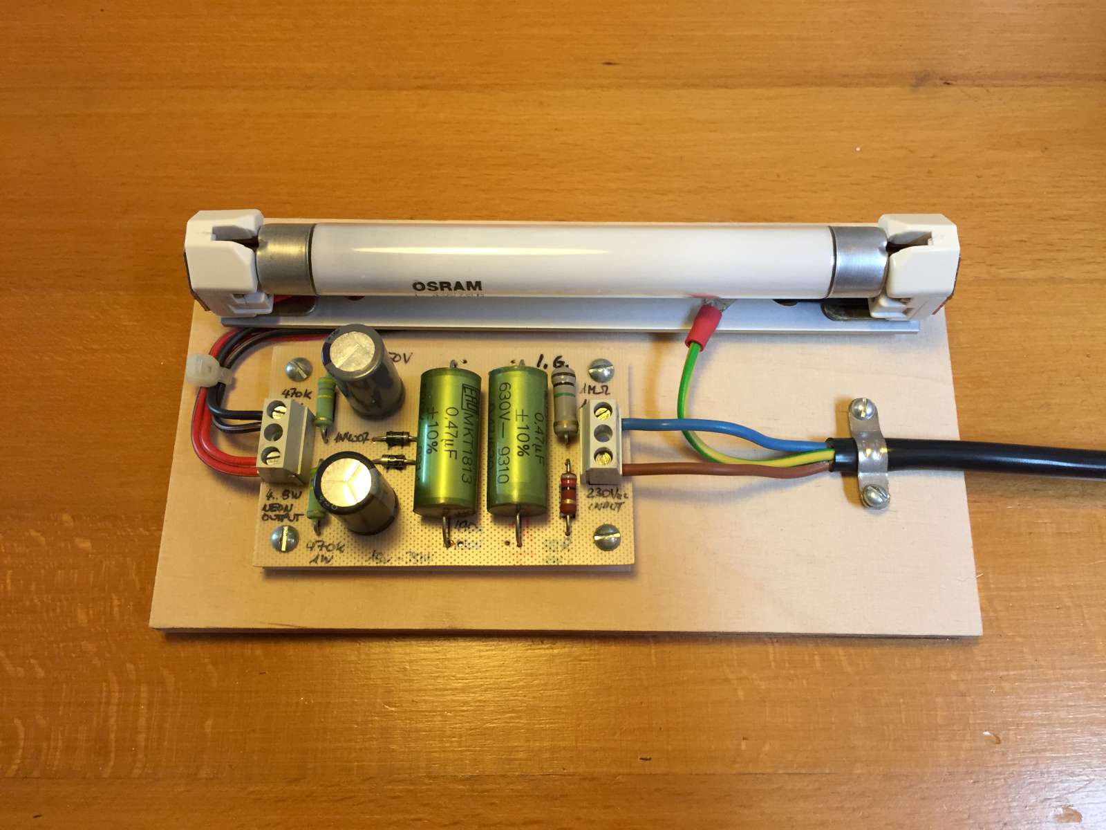
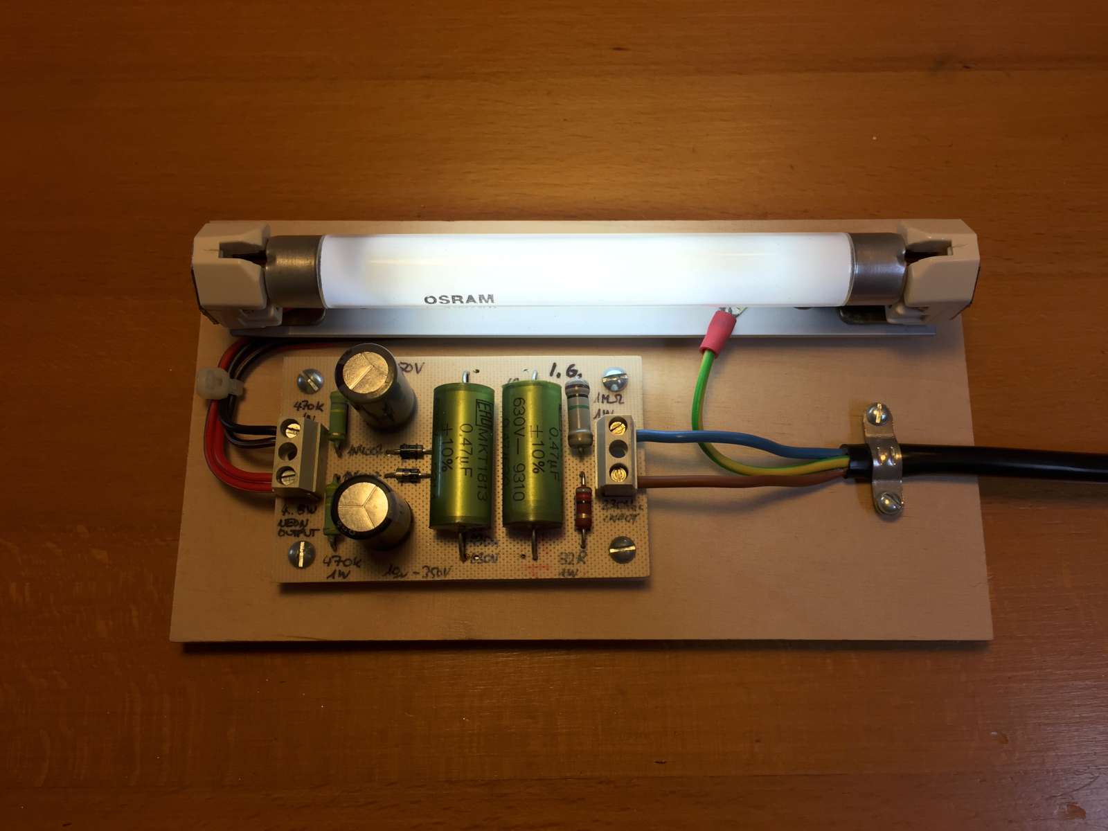
Pictures of the lamp. (click to enlarge).
When the lamp is on, one can remark that the negative electrode (in the picture on the left) is darker than the positive one: this is due to the Faraday dark zone, typical of low pressure gas discharges, that is only visible when the tube is powered with DC current.
As I said, it's a nice, unusual, funny and dangerous circuit. Definitely didactic to learn how fluorescent tube work but not good enough to replace a conventional AC ballast circuit.
| Home | Electronics | Page hits: 101927 | Created: 07.1999 | Last update: 03.2018 |