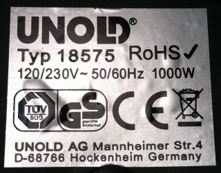
Boiler label with voltage and power ratings.
In order to test and optimize the long and medium-waves transmitter described in another page of this site, I needed a dummy load capable of handling about 1 kW of power. Of course the best solution is to buy a professional one, but they are pretty expensive, so I looked for another solution.
I remember a colleague of mine telling me that in his previous job, in winter when it was too cold in the lab, he used to connect directly a nice Bird 50 Ω / 1.5 kW dummy load with the mains supply (230 V / 50 Hz). Well, why not? Professional dummy loads are rated something like DC to 1 GHz (or more), so 50 Hz are well in spec, and 230 V over 50 Ω make exactly 1058 W: what a nice (but expensive) heater!
Now the question is: can we make the opposite? Can we take a simple mains supply 1 kW heater and use it as an RF dummy load? Well, real dummy loads are designed with non-inductive resistors that ensure an extremely wide frequency range, while regular heaters use coiled resistors that have significant stray inductance. But long and medium-waves have low frequencies and maybe the inductance can be neglected. There is only one way to find out if it works: try with a real heater.
One day, while I was waiting for a salesman in a consumer electronic store, I stepped into a portable water boiler, rated 1000 W 120/230 V 50/60 Hz, for a very good price. The advantage of the water boiler is that when the water boils, it's possible to throw the hot water in the sink (or make some tea) and replace it with cold water and start again. When nice oil-immersed dummy loads run too hot, one has to wait hours before they cool down.
Boiler label with voltage and power ratings.
So, I bought that boiler and took it apart: all the wiring, thermo switches and security fuses were removed, since a device that disconnects the load when it becomes too hot would have a terrible effect on the transmitter under test.
This boiler has two resistors: one for the 120 V mains and one for the 230 V one. The first one measures only 14.7 Ω and is useless four our application, but the second one measures (when cold) 54.3 Ω: a bit higher than the expected 52.9 Ω, but acceptable.
Resistors are temperature dependent, especially when not designed to be precise. To be sure that the resistance will not vary too much when hot, I boiled some water and re-measured the resistance right after disconnecting the power. The thermometer reads 90 °C and the resistance is 53.8 Ω, only 0.5 Ω less than the 54.3 Ω measured at 20 °C: not a big deal and closer to 50 Ω anyway. The only curious thing is that the resistance of this boiler actually decreases with temperature while usually metals have the opposite behavior, but again, not a big deal.
So connecting a 50 Ω coaxial cable to the 54.3 Ω resistor is enough. Don't forget to connect the metal chassis to the shielding of the cable to avoid (RF) burns when touching the boiler. Of course it will become hot, as any regular boiler would do. Adding thermal insulation over the wires is a good idea, and in any case you'll find the suitable insulation tubing already in the boiler, so no need for extra parts.
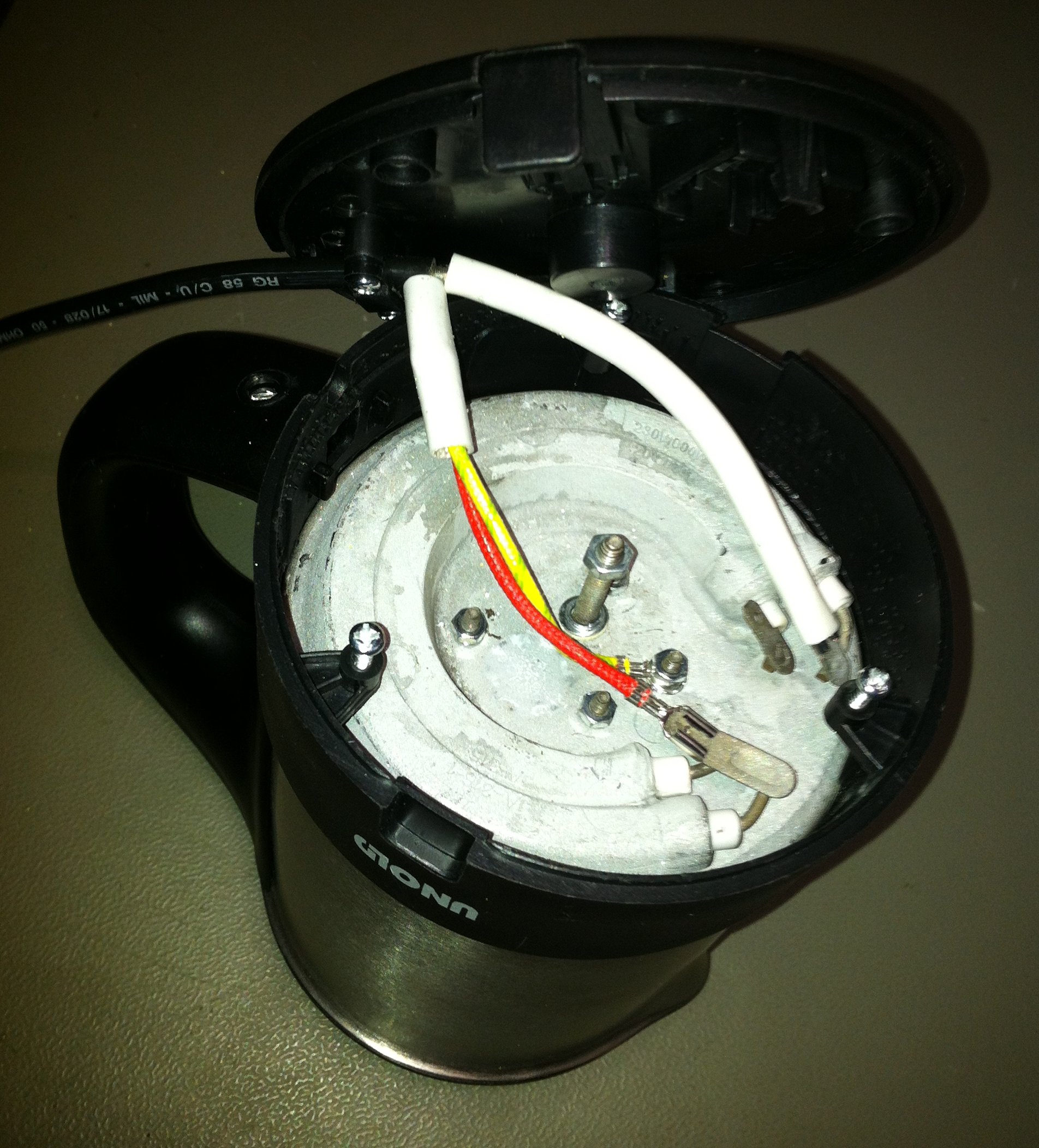
Boiler resistor connections (click to enlarge).
The boiler is made of stainless steel in which the heater resistor is buried. I measured therefore the capacitance between the resistor and the case and I found 123 pF: low enough to be neglected at long- and medium-waves where it introduces a stray reactance of respectively 9.5 kΩ and 2.5 kΩ in parallel with 50 Ω, but too high to use this boiler for short-waves or higher frequencies.
Ok, there is still hope this boiler will work for our application: let's connect it to the network analyzer and see how it behaves:
VSWR plot, 100 kHz to 2 MHz.
Well, the VSWR is low at low frequencies and rises with increasing frequency, typical of stray inductance: no surprise so far. At 137 kHz the VSWR is about 1.2:1 making this boiler a pretty good dummy load. At 500 kHz the VSWR has already rised to 1.8:1: not as good as before but still acceptable. At 1.8 MHz we get 3.7:1 making this load completely useless for short-waves.
It's now interesting to determine the stray inductance that limits the bandwidth of this load. To do so, adding a known capacitor in series with the load will neutralize the effect of the inductance at a given frequency and its value can be calculated. I used a 1 nF ceramic capacitor (actually 950 pF when measured) and found that the VSWR now has a minimum at 1.74 MHz as visible in the two pictures below that show the behavior with and without series capacitor. This capacitor was deliberately selected much higher than the stray capacitance we measured before in order to minimize its effect.
VSWR plot, 100 kHz to 5 MHz.
VSWR plot, 100 kHz to 5 MHz with 950 pF in series.
It's now possible to calculate the value of the stray inductance that is 8.8 μH in this case. This can be neglected at 137 kHz since it represents only 7.6 Ω in series with 50 Ω. At 500 kHz it's already 28 Ω and starts to increase the VSWR. At 1.8 MHz it becomes 100 Ω, way too much to be ignored.
The equivalent circuit is represented below and it's basically composed by a load resistor of 54.3 Ω in series with a stray inductance of 8.8 μH, both in parallel with a stray capacitance of 123 pF:

Equivalent circuit.
Now, we know that water has a mass specific heat capacity Cp of 4.18 J/(g·K), meaning that 1 kW of power increases the temperature of 1 kg of water by 14.3 °C every minute. Since this boiler only holds 0.5 l, the same power should rise the temperature twice as much in the same time (by 28.6 °C).
To verify the heat efficiency of this boiler, I heated 0.5 kg of water with 1 kW of electrical power and monitored the temperature with a thermometer: it took 52.5 seconds to rise the temperature by 20 °C (from 35 °C to 55 °C). This corresponds to a heating power of only 800 W, the remaining 200 W actually heats the boiler itself, the surrounding environment and contribute to evaporate the water. The efficiency is therefore 80 %. Simply by measuring how fast the RF heats the water, it's possible to determine quite precisely the power supplied by the transmitter by using the following relation:
Where P is the power in Watts, m is the mass of water in kilograms, ΔT is the temperature rise in °C, Δt is the time it takes to rise the temperature by ΔT in seconds, η is the efficiency of the boiler (0.8 for 80 % in this case) and 4180 J/(kg·K) is, of course, the mass specific heat capacity of water.
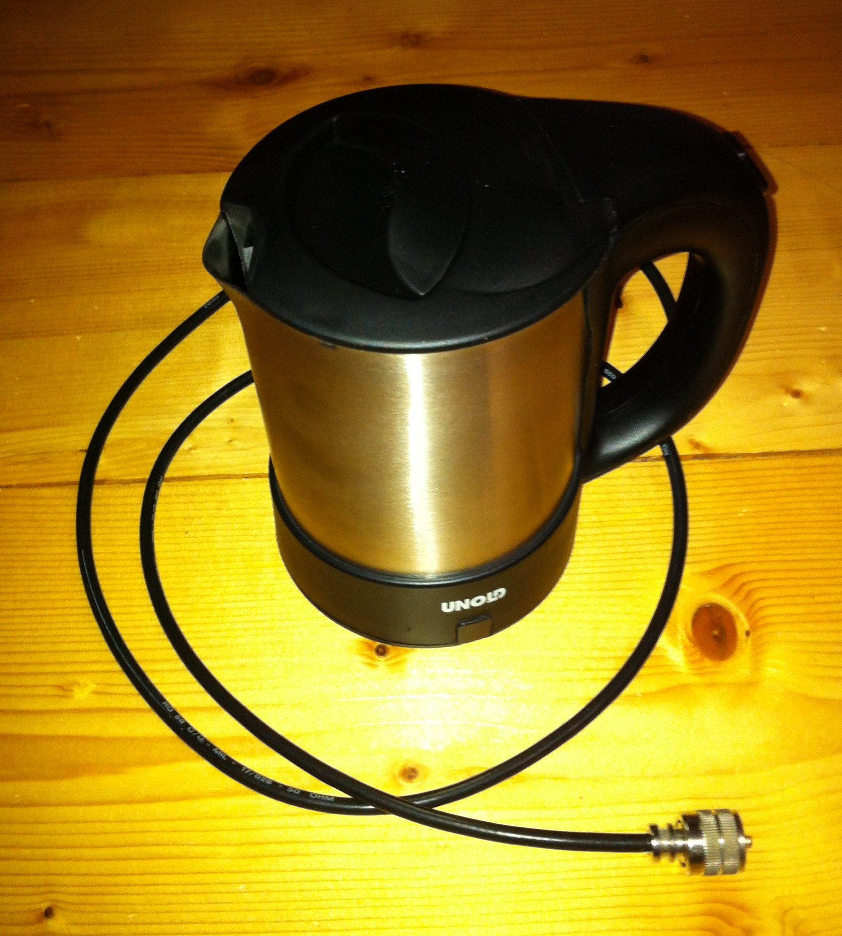
Assembled dummy load (click to enlarge).
The dummy load presented here is simple, cheap, easy to build, and doesn't require any strange component. Because of its stray reactances, it only works well for long-waves and has an acceptable behavior in the lower part of the medium-waves, let's say up to 600 kHz. It has even some more advantages: when the water boils, it's easy to replace it with cold water and start again. As long as there is water inside, there is no risk of overheating (water never runs hotter than 100 °C at ambient pressure!). Even if the all the water would boil out damaging than the boiler, buying a new one will not ruin you. Burning a professional dummy load would be a much more inconvenient (and expensive) story.
The two plots below show the VSWR for the 137 kHz and 500 kHz bands.
VSWR plot, 100 kHz to 150 kHz.
VSWR plot, 450 kHz to 500 kHz.
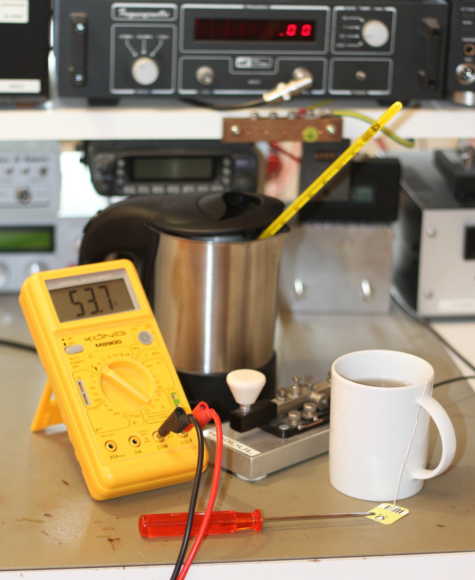
Power measurements and a cup of tea (click to enlarge).
| Home | Electronics | Page hits: 021293 | Created: 06.2012 | Last update: 06.2012 |