Picture of a lightning strike.
Many years ago, I think it was in 1997, I stepped into an interesting circuit on a book about high voltage [1]. It was the diagram of a simple "lightning flash counter" intended to help in designing lightning protections on power lines. The description was very brief, but following the bibliography reference, I could find the original article [2], published in May, 1972. I always had a fascination with lightning strikes and I decided to build the circuit, just for fun.
Picture of a lightning strike.
If you ever wondered, for a given region, how many strikes are there in a thunderstorm, what is their frequency, how many storms happens every year, how many days are stormy every year (this is almost the definition of "keraunic activity") or what is the average duration of a storm, this circuit will provide some answers.
Long exposure with several lightning strikes.
According to the original article, it also allows (roughly) estimating how many strikes hit the ground per square kilometer every year. This can be valuable information when, for example, installing surge arrestors on your antenna feeder lines.
Some pictures of lightning strikes can be found here.
To count the strikes, we need and adequate sensor. This circuit uses an antenna to sense the variations in the electrical field. The original article suggested to suspend six 14 m long, parallel wires, 5 m ±20 cm above ground as summarized in the diagram below:
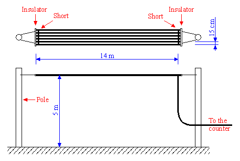
Diagram of the antenna.
The static capacitance to ground of the antenna should be around 220 pF.
The wires must be well insulated from ground and all shorted together. This antenna must be located in a reasonably flat and clear area, far away from overhead power lines.
This setup is excellent for a power company with "unlimited" space and budged, but was a bit too demanding for me: I decided to install the antenna wires under my roof. There is less clearance and it's not flat (but the slope has an average height of about 5 m) but there are no poles to install, no guy wires, no extra space required and it turned out to work quite fine.
The other end of the counter must be grounded. I used the steel water supply pipe as ground connection. I measured its ground resistance and found 3.6 Ω, which is more than fine, since the original article requires a ground resistance less than 100 Ω.
The circuit of this lightning flash counter is quite simple: only four transistors.
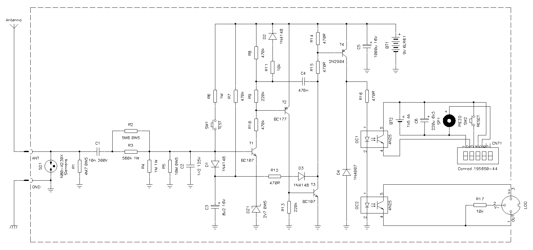
Schematic diagram of the counter (click to enlarge). –
A PDF version is also available:
lightning-diagram.pdf
(35,559 bytes).
It all begins with antenna and ground connected to the two input terminals on the left. First, the surge arrestor SG1 takes care (within reason) of high voltage pulses that may come from the antenna. Of course, it will not survive a direct lightning strike. The model used here, a Siemens N80-A230X, will spark over at 230 V ±20 % and resists a 20 μs pulse of 12 kA; any similar arrestor will do the trick. Resistor R1 provides a DC path to ground to slowly discharge any charge that may accumulate on the antenna.
The input filter is composed by C1, R3, R3, R4, R5 and C2. It's a band-pass filter designed for a center frequency of 500 Hz and –3 dB points at 100 Hz and 2.5 kHz. This configuration has been selected by the author of the original article to make the difference between lightning strikes and other kind of electromagnetic noise. Up to here, power resistors and high voltage capacitors are required. Also make sure the insulation is good. For better accuracy 1 % precision parts would be a better choice.
The four transistors compose a one-shot monostable section. At idle, all transistors are blocked. When the voltage on T1's base rises above 3.4 V, it starts conducting. This threshold voltage is due to the usual base-emitter voltage of 0.7 V plus 2.7 V introduced by the Zener diode DZ1. In the original circuit, two mercury cells in series were used to have a nice and stable 2.7 V on T1's emitter. But mercury cells were banned long ago, so here a Zener diode is used instead: it's probably a little less accurate (low voltage Zeners do not have a very sharp knee in their voltage-current characteristic) but requires no maintenance.
As T1 starts conducting, T2 and T3 will amplify its current and conduct as well. The positive feedback introduced by C4 makes the circuit latch until C4 is fully charged; this takes about 250 ms with 470 nF. When T3 conducts, it discharges C3 and forces, via D1, the base of T1 to a low potential preventing another count before C3 is recharged again. With 8.2 μF, this takes about 1 second and prevents multiple counts for the same strike.
This part is powered by BT1, a 6LR61 9 V cell. Since the power consumption is lower than 1 μA (when no strikes are detected) the battery will last for a few years. For the circuit to work, the voltage should be at least 6.5 V. The test button SW1 allows checking if the battery is still good: when pressed and held down, the counter should tick about once per second.
T4 is the output transistor and it's turned on every time T3 conducts. On its collector, two optocouplers OC1 and OC2 drive the digital counter and the external logger. The original circuit used an electromechanical relay instead and diode D4 was there to protect T4 from surges generated by the inductance of the coil. There is no need of D4 with optocouplers and you can skip it: I included it because when I first built this circuit, I wasn't sure about what kind of load I wanted to connect, than I choose optocouplers and left D4 in since it was already there and didn't harm.
Instead of an old fashioned electromechanical counter, I used a digital 5-digits LCD counter CNT1 powered by BT2, a single LR6 (AA) 1.5 V cell. The power consumption of this counter is about 1.5 μA and the battery lasts for a few years. I choose to use a separate battery for CNT1, because a voltage regulator to power it from BT1 would either have been very complex or have increased the idle current, significantly reducing battery life. This counter has a reset switch SW2 and a piezo speaker that beeps on every count. This short beep turned out to be quite a nice feature because it tells you that a storm is coming a few minutes before you start hearing thunders, especially if you're indoor. By the frequency of the beeps, you can better judge the intensity of the storm, since not all strikes make an equally loud thunder.
Any other counter should work fine (even mechanical ones) but the connections may require some modifications. The insulation provided by the optocoupler OC1 here is not necessary: I just used an optocoupler to adapt the two different supply voltages (9 V and 1.5 V) because it was easier. A transistor and a resistor could do the trick as well. A 6 or 9 V DC counter can be directly connected between the collector of T4 and the ground (but in this case D4 may be required).
The other optocoupler, OC2, interfaces this circuit with an external logger. Here the insulation of the optocoupler is necessary to avoid any ground problem, especially when using a PC as logger. PC power supplies are not always grounded and often their chassis is at about half mains voltage.
This circuit is not critical and many parts can be replaced with similar ones. It's a good idea to mount all the parts inside the dashed lines in a grounded metallic box. If mounted outdoors, the box must also be weather proof.
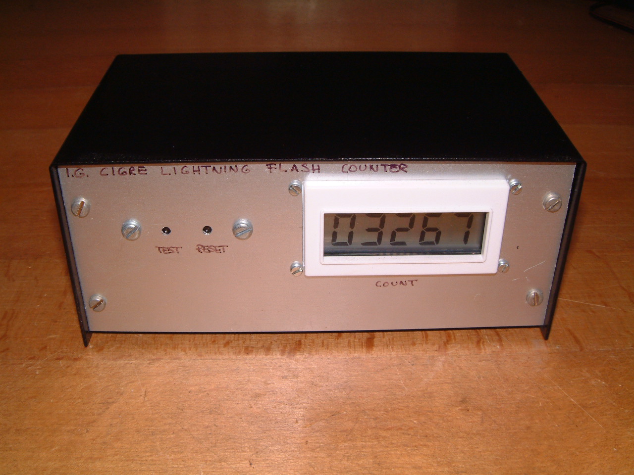 This is the front panel of the counter, please remark the two switches ("test" and "reset") and the 5-digit counter. |
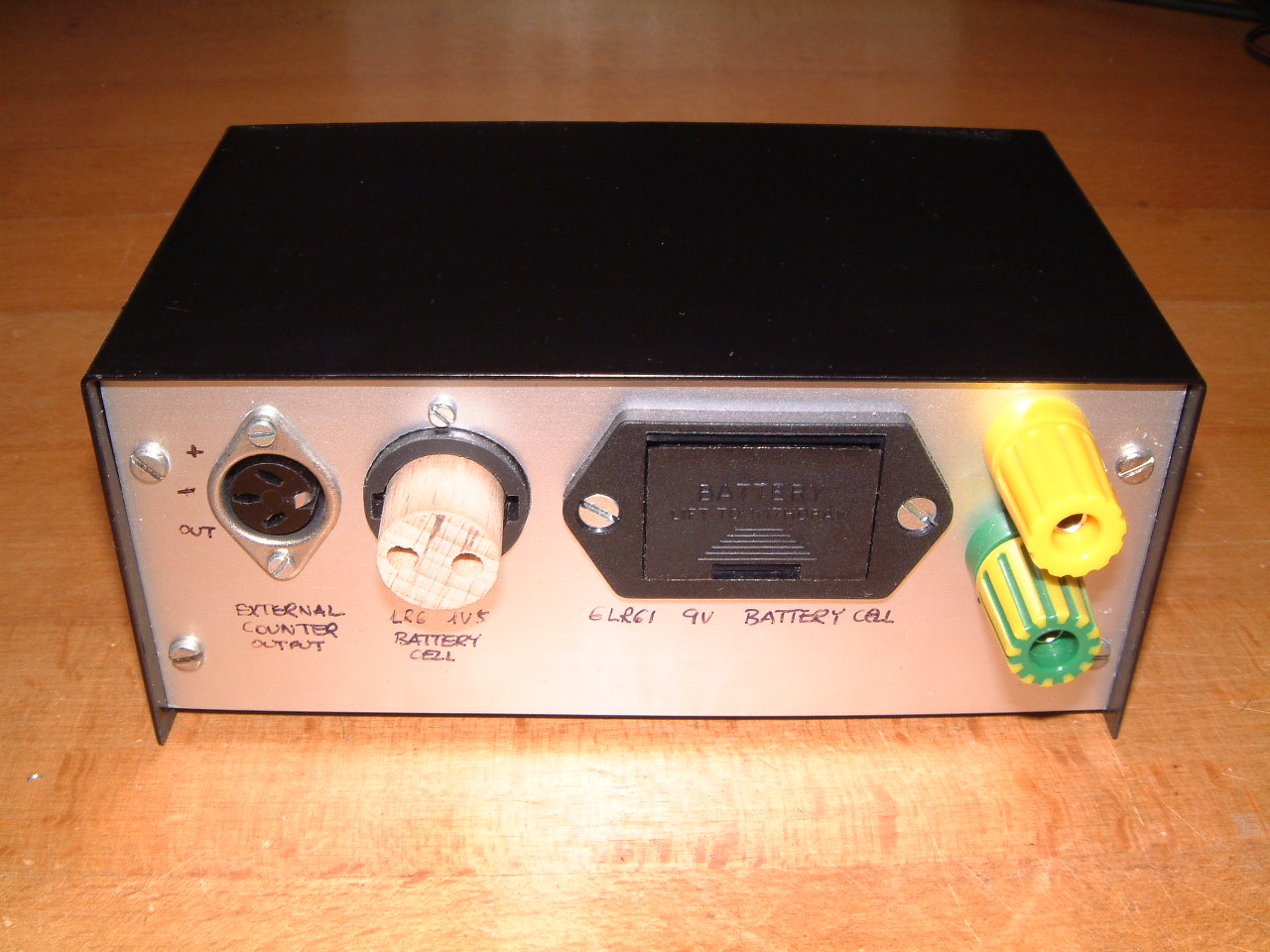 On the rear panel, the interface connector, the 1.5 V battery holder, the 9 V battery holder and the antenna / ground connectors (from left to right). |
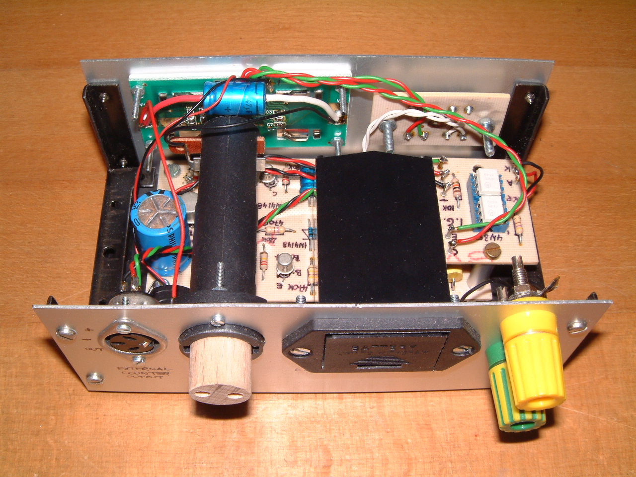 Inside view of the counter. The main circuit board is on the bottom. |
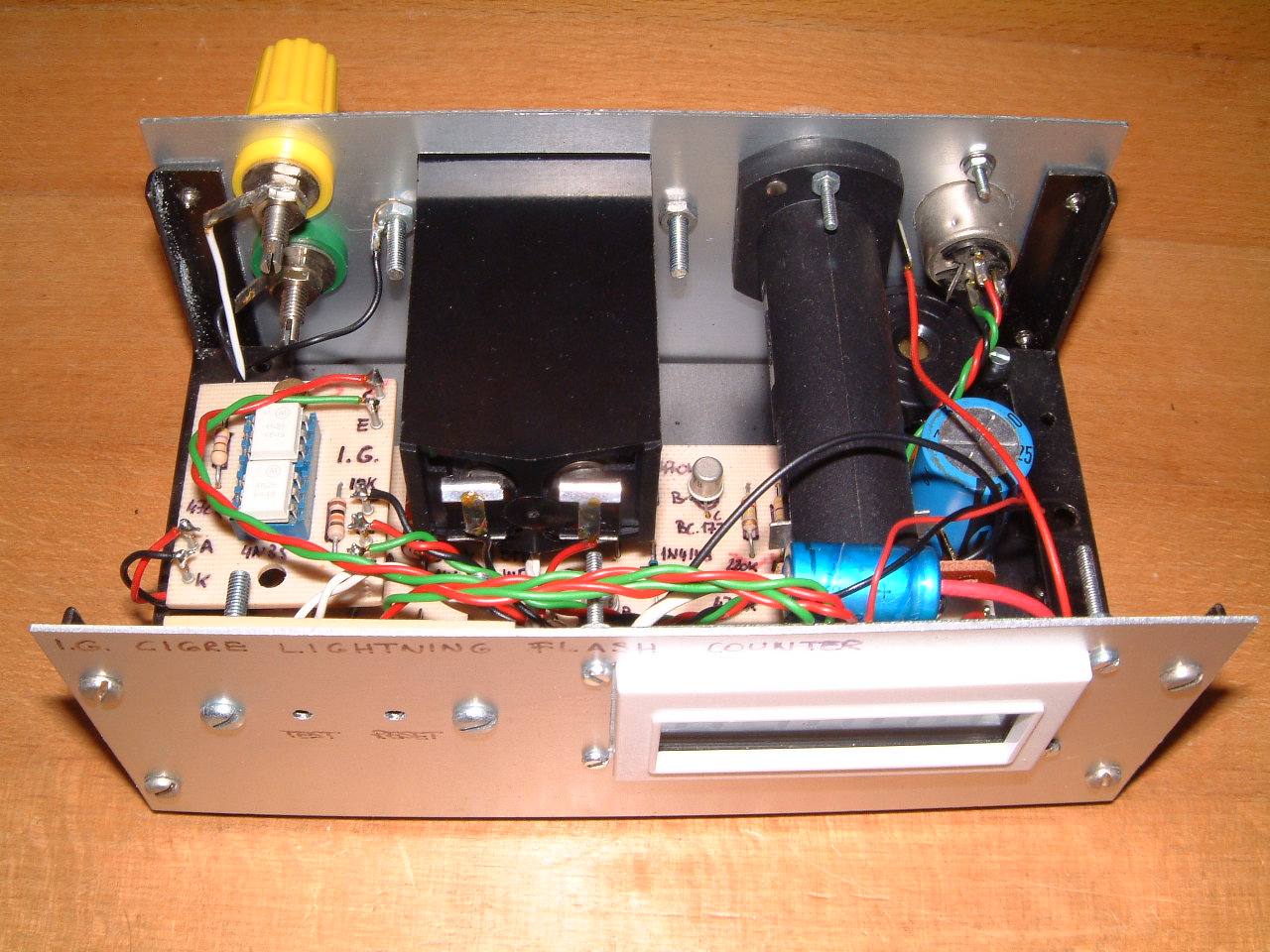 Another inside view of the counter. As you can see there is not much space left... |
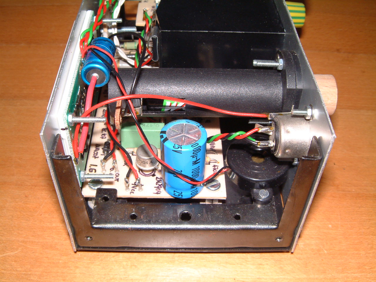 On the right side the piezo speaker and the big 1000 μF filter capacitor. |
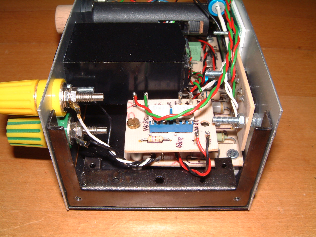 On the left side the two optocouplers to connect the internal counter and the external logger. |
Counting the number of strikes every year is nice, but logging when exactly each strike happened is even better. It happened that back in 1998 I had an old 386-based laptop with a broken screen: the perfect candidate to implement a simple logger. The main advantage of a laptop computer is that it has its own battery and easily survives the short power outages that always happen during lightning storms. So, I connected the counter to the laptop via the RS232 cable and wrote a small logger program in Turbo Pascal, running under MS-DOS. The cable diagram was the following:
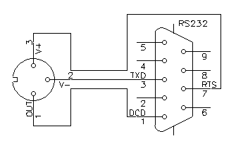
RS232 connection cable.
The RTS line is set at +12 V by the logger software providing the positive supply, while the TXD line (not used for communication) is idle at –12 V providing the negative supply. The optocoupler OC2 in the counter pulls the DCD line high for about 250 ms every time a strike is detected allowing the program to log them.
This worked from Aug. 19, 1998 until Sep. 13, 2000 when the laptop finally died. I suppose laptops are not designed for 7/24 operation. In the following years, I looked for another old and very cheap laptop to start logging again, but couldn't find any. On the other hand, I didn't want to use too much energy to keep the logger running and wasn't fully satisfied by the laptop solution. In the meantime, operating systems and programming languages completely changed making my simple logger program completely obsolete and useless.
One day in November 2013, a friend of mine suggested to use an Arduino board to make a simple logger. He was right: I ordered an Arduino Uno board and a data logger shield. After connecting them together and a couple of evenings of programming the logger was ready.
It has all the required features: it's quite cheap, easy to build, doesn't require as much power as a laptop, doesn't make any noise, survives short power outages without battery and writes on a normal SD-card.
The schematic diagram is simple and straightforward: the Arduino Uno board contains the CPU, the clock source, the power supply and the USB interface. On top of this board is plugged the data logger shield containing a DS1307 based real time clock (RTC), an SD-card reader and some "prototype space" to install additional components. Both boards are represented as a single block in the following schematic diagram:
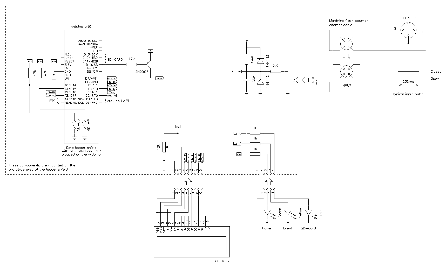
Schematic diagram of the logger (click to enlarge). –
A PDF version is also available:
logger-diagram.pdf
(45,948 bytes).
The logger is based on an Arduino UNO board, a data logging shield (SD-card plus RTC) and a 16×2 LCD display. Each time a lightning strike is detected the date and time is recorded in a log file on an SD-card. The RTC has a battery backup and keep running even in case of power outage (frequent during storms).
Events are represented by an optocoupler shorting for about 250 ms each time a strike is detected. This triggers our logger via a digital input PIN.
Three LEDs signal the status of the logger. A green power LED connected on the power supply tells that the logger is powered up. A yellow LED connected on a digital pin echoes the input for checking the connection with the strike detector. This LED only works when the logger is ready to log. The yellow LED blinks in case of error telling that the logger is not functioning anymore. A red LED, connected on the SD-card chip select line, tells when the SD-card is accessed. This LED is connected via a PNP transistor, not to load too much this line.
Since I didn't want to add buttons and menus, each time the logger is started
(powered on), it looks on the root of SD-card for a file called
SETTIME.CLK.
If found, it will use it for adjusting the RTC.
If the operation is successful, the file is deleted to prevent readjusting
the clock on a wrong time if the logger is powered off and on again.
Only the first 19 characters of this files are read, and the format is
YYYY-MM-DD HH-MM-SS (for example 2014-01-17
21:15:00)
and leading zeros are required.
See SETTIME.TXT for a file template and detailed instructions.
In order to avoid readjusting the RTC twice a year for daylight saving time,
using UTC is probably a good idea.
Each time the logger starts, it will log it.
Then, every time the input signal level drops (idle high, active low) the
date and time are logged.
Log file names are composed by the year and the month:
2014-01.LOG, for example.
There is one log file per month and they are all located in the SD-card root
directory.
If nothing happens during one month, no file is created.
All logged information is also echoed on the virtual RS232 port over the USB
for monitoring with a PC.
The structure of the log files can be easily imported with common spreadsheet software (like Excel) that can also calculate some statistics in just a few clicks.
This is an example of the log file:
2013-08-17 11:15:43 - 0 - Log session started.
2013-08-17 20:18:39 - 1 - Lightning strike detected.
2013-08-17 20:19:21 - 2 - Lightning strike detected.
2013-08-17 20:19:26 - 3 - Lightning strike detected.
With Excel you can just import the log file as a text file and split it into
columns: one for the date and one for the time.
The other columns are not very important and can be deleted, but keep only
records marked as " - Lightning strike detected.".
Then, the FREQUENCY(xx:xx;yy:yy) function allows counting the
events and separate them in classes.
This logger cannot operate without SD-card. The SD-card must previously be FAT or FAT-32 formatted, must not be write protected and must have sufficient space available.
The firmware (program) used for this application is available here (as freeware): logger-firmware.zip (12,510 bytes).
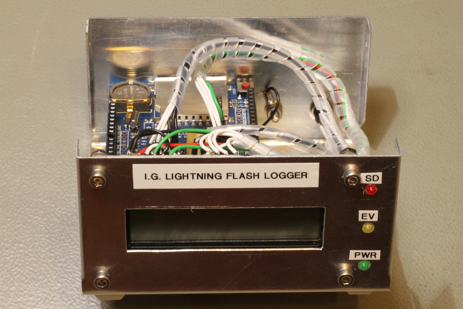 Front view of the lightning logger (click to enlarge). |
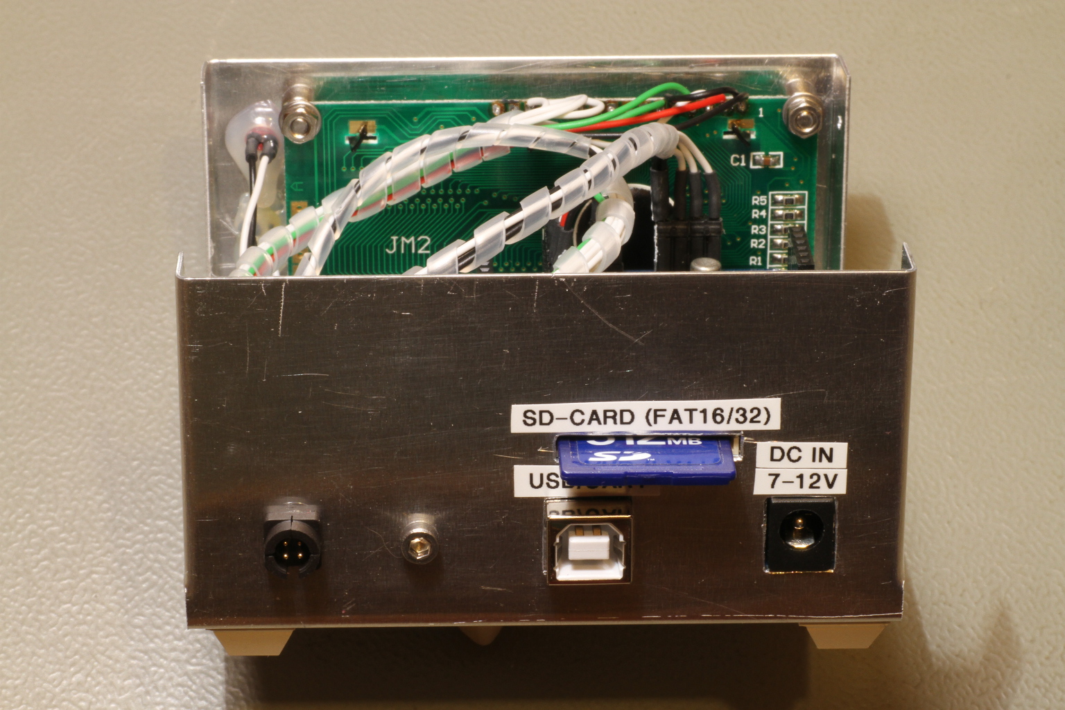 Back view of the lightning logger (click to enlarge). |
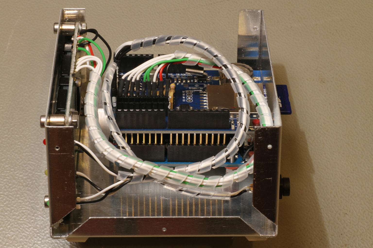 Side view of the lightning logger (click to enlarge). |
At the beginning I faced a bizarre problem: the RTC clock was running way too fast, something like a few minutes per hour, while it wasn't fully responding as expected to the I2C commands. The RTC part of the data logger shield is extremely simple and only counts three components: a DS1307 chip, a 32.768 kHz crystal and a CR1220 lithium cell. Now, the battery was easy to check and was in good shape, so I suspected the crystal. But after replacing it the problem persisted. There was only one suspect left: the DS1307. After ordering a new DS1307 chip to an official Maxim dealer, I was surprised to remark the two IC do not look the same, as one can see in the following picture. After replacing the IC, the RTC was working as expected. I don't know how this can be explained; my guess is that the original IC mounted on the shield is a fake one.
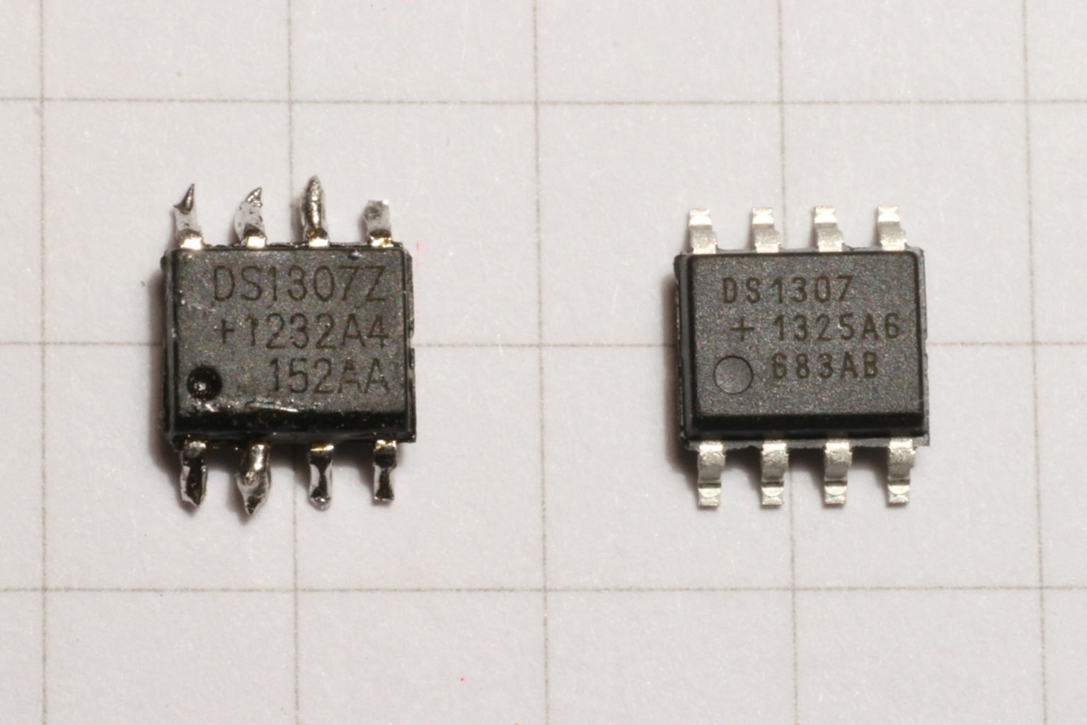
Picture of two DS1307 integrated circuits.
The one on the left doesn't work properly and is probably a fake, the one on
the right is a genuine Maxim DS1307 and works fine. (click to enlarge).
The logger is powered by a wall mounted AC-DC adapter providing 9 VDC. The big internal electrolytic capacitor of the power supply is enough to keep the logger powered on for e few seconds if the AC power fails during a storm.
The keraunic level is defined as the average number per year where a thunder is heard at least once. The value taken from an isokeraunic map for the location where the counter is located is 50 to 55 [1].
For the calculations in this page, since we have a lightning counter and it's not practical to manually record if the thunder was heard or not, we calculate the keraunic level as the number of days per year where the counter increments by one or more counts. It's not exactly the same thing, but close enough.
Counting and logging lightning strikes is a lot of fun, but this counter can also be used to estimate the average number of strikes hitting the ground. This provides useful information if designing lightning protections. In the original article [2] a method for calculating the ground strike density is explained, that is applied here without any further discussion.
The ground flash density Ng expressed in strikes per year and per square kilometer is given by:

Where N is the number of strikes counted by this detector, Rg is the detection range in kilometers of this detector for strikes hitting the ground (the author suggests Rg = 30 km) and Yg a correction factor calculated as follows:
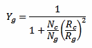
Where Rc is the detection range of this detector for strikes between clouds (the author suggests Rc = 20 km) and Nc/Ng is ratio of clouds strikes to ground strikes. If this ratio (for the considered region) is known, it should be used. If not, it can be estimated with the following equation:

Where K is the keraunic level described above.
Let's take an example: in 1999 the counter recorded N = 1729 strikes distributed on a total of K = 64 days (in the 301 other days of the year, no strike was recorded). Let's also assume Rc = 20 km and Rg = 30 km. We can calculate Nc/Ng = 4, than Yg = 0.36 and finally Ng = 0.22 strikes per year and per square kilometer.
This lightning flash counter was installed close to Lugano, Switzerland, (46° N / 9° E) on August 19, 1998 and was shut down on July 8, 2024, because a nearby solar panel installation started to interfere with the counter. During this 25 years long period, at the end of each year, the counter is recorded, reset and analyzed.
The following chart and related table show the results:
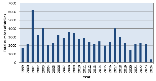
Number of lightning strikes per year.
| Year | Total number of strikes |
Average strikes per day |
In average, one strike every |
Keraunic level |
Ground strike density per km2 |
Note |
| 1999 | 1729 | 4.7 | 5 h 04 min | 65 | 0.22 | (1) |
| 2000 | 2141 | 5.8 | 4 h 06 min | N.A. | 0.29 | (2) |
| 2001 | 6243 | 17.1 | 1 h 24 min | N.A. | 0.83 | (2) |
| 2002 | 3267 | 9.0 | 2 h 41 min | N.A. | 0.44 | (2) |
| 2003 | 4065 | 11.1 | 2 h 09 min | N.A. | 0.54 | (2) |
| 2004 | 2046 | 5.6 | 4 h 18 min | N.A. | 0.27 | (2) |
| 2005 | 2333 | 6.4 | 3 h 45 min | N.A. | 0.31 | (2) |
| 2006 | 3267 | 9.0 | 2 h 41 min | N.A. | 0.44 | (2) |
| 2007 | 2896 | 7.9 | 3 h 01 min | N.A. | 0.39 | (2) |
| 2008 | 3607 | 9.9 | 2 h 26 min | N.A. | 0.48 | (2) |
| 2009 | 3471 | 9.5 | 2 h 31 min | N.A. | 0.46 | (2) |
| 2010 | 2770 | 7.6 | 3 h 10 min | N.A. | 0.37 | (2) |
| 2011 | 2882 | 7.9 | 3 h 02 min | N.A. | 0.38 | (2) |
| 2012 | 2476 | 6.8 | 3 h 33 min | N.A. | 0.33 | (2) |
| 2013 | 2186 | 6.0 | 4 h 00 min | N.A. | 0.29 | (2) |
| 2014 | 2492 | 6.8 | 3 h 31 min | 75 | 0.30 | |
| 2015 | 2001 | 5.5 | 4 h 23 min | 68 | 0.25 | |
| 2016 | 2400 | 6.6 | 3 h 40 min | 77 | 0.29 | |
| 2017 | 4030 | 11.0 | 2 h 10 min | 63 | 0.52 | |
| 2018 | 3022 | 8.3 | 2 h 54 min | 78 | 0.36 | |
| 2019 | 2308 | 6.3 | 3 h 48 min | 72 | 0.28 | |
| 2020 | 1513 | 4.1 | 5 h 48 min | 57 | 0.20 | |
| 2021 | 2144 | 5.9 | 4 h 05 min | 57 | 0.28 | |
| 2022 | 2320 | 6.4 | 3 h 47 min | 62 | 0.30 | |
| 2023 | 2166 | 5.9 | 4 h 03 min | 76 | 0.26 | |
| 2024 | 363 | 1.9 | 12 h 30 min | 24 | 0.06 | (1) |
| Notes: | |
| (1) | Because in 1999 and in 2024 the counter was not active for the whole year only partial data is available: 135 days in 1999 and 189 days in 2024. More specifically, the most active summer season is only partially recorded and yields to inaccurate results. |
| (2) | Unfortunately, from 2000 until 2013 no logger was available; only the annual count was recorded. Without a daily record, for these year, it's not possible to calculate the keraunic level. So for calculating the ground strike density in this period, a default value of 55 has been used. |
In this region, thunderstorms are clearly a seasonal phenomenon with peak activity in summer (say May to September) and almost no activity in winter (November to March), as one can see in the following chart summarizing the total number of strikes per day in 1999.
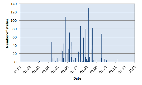
Number of lightning strikes per day in 1999.
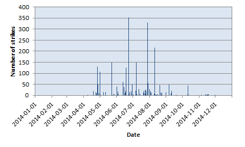
Number of lightning strikes per day in 2014.
This seasonal behavior is quite handy for planning maintenance operations to a lightning protection system, or to this counter itself. By collecting and resetting all logged information at the end of each year, there are very little chances of splitting a storm in half between two consecutive years. And the exact moment when the counter is reset to zero is not very important neither, because almost no strike are detected in December and in January. So, there is no need to stand in front of the counter on December 31 to read its value at 23:59:59... it won't change for at least one month. But keep in mind that this seasonal behavior may be different in another region.
| [1] | M. Auget et M. Ianoz. Traité d'Électricité, Vol. XXII: Haute tension. Presses Polytechniques et Universitaires Romandes, 1990, section 3.6. |
| [2] | S. A. Prentice. Compteur de coups de foudre. Electra CIGRE, No 22, May 1972, pages. 149-179. |
| Home | Electronics | Page hits: 103284 | Created: 09.1999 | Last update: 01.2025 |