Circuit diagram of the power supply unit (click to enlarge). – A PDF version is also available: powercircuit.pdf (39,750 bytes).
The power supply unit is responsible for providing the necessary DC power supply to the whole transmitter. Two DC voltages are required: 13.2 V for the control circuits and 40 to 48 V for the power amplifier. The first voltage is not a big deal, the whole system only uses less than 500 mA for its control circuits, but the power amplifier is a different story: up to 25 A are required (no wonder if we want a kilowatt at the output).
Several options have been considered. The first idea was to use an industrial 48 V power supply; these modules are pretty common since they are widely used for telecom applications, but I couldn't find any at a reasonable price. If you can find one, beware that very often the positive terminal is grounded and problems may arise when trying to isolate the positive to ground the negative terminal, as required by this circuit.
The second idea was to use four 13.8 V 25 A amateur station power supplies in series. As a plus, this option allows decreasing the supply voltage (and the output power) by connecting only three or two units if required. This idea was also discarded because of the price of four such units. If you find them, you should beware about two things. First make sure that the DC output of each unit is isolated from ground, otherwise it won't be possible to connect them in series. Than you should protect each unit with a strong silicon diode in parallel with each output, to prevent the units to destroy each other during start-up and shut-down phases (if a unit starts before the others, it will feed the other units through the load in reverse polarity!!!). The diodes must be able to carry the full current (say at least 25 A) and must be connected in order to be normally blocked (cathode to the positive terminal and anode to the negative one).
Finally HB9ASB gave me a nice toroidal transformer capable 550 VA. It's not 1200 VA as I wanted, but more than enough for having some fun with this transmitter. If one day I find a better transformer, I'll update this power supply, but for the moment I'm fine with it.
The schematic is visible in the figure below and it's a very classical linear power supply:
Circuit diagram of the power supply unit (click to enlarge). –
A PDF version is also available: powercircuit.pdf (39,750 bytes).
Even if this circuit is pretty straightforward, I still would lake to spend some words: the mains supply connects to CN2, is protected by the two fuses F2 and F4 and filtered by FLT1. SW1 is the power switch and LN1 indicates the status of the power supply. The snubber network composed by R2 and C14 absorbs inductive spikes caused by the inductance of the transformers when SW1 is operated, preventing sparks from appearing in the switch. NTC1 is an inrush current limiter that protects mainly the rectifier bridges from the huge current spike generated when the unit is first switched on and all the capacitors are still discharged. It also prevents the fuses from blowing if the mains line is heavily loaded. It's designed to have a cold resistance of 5 Ω and allows a maximum of 5 A.
One single transformer with 2 secondaries would be best, but I couldn't find one, so I had to put two different transformers. TR2 is the auxiliary transformer used to generate the low current 13.2 V for the control circuits. This section is designed to deliver up to about 1 A. The voltage is rectified by D2 and smoothed by C15 and than stabilized by U1, a good old LM7812. The standard 12 V voltage of this regulator is raised by 1.2 V by diodes D3 and D4 obtaining 13.2 V at the output. C16 and C17 prevent U1 from oscillating and must be mounted close to its terminals. F3 protects the circuit against an accidental short circuit and LD2 informs about the status of the fuse.
Transformer TR1 is the power transformer. It has two equal windings that are connected in parallel (beware of the phase!). D1 is the rectifier bridge and is probably a bit oversized; a 35 A 200 V model should be enough. It runs pretty warm and deserves a small heat sink.
Smoothing the voltage is not an easy task because the current is high (up to 25 A) and requires a huge capacitor. I could find in my junk-box twelve 10'000 μF 100 V electrolytic capacitors that connected in parallel together give an amazing 0.12 F! With such a capacitance the output ripple is about 2 V at 25 A. It's important to keep the ripple low, since this will AM-modulate the RF in the final unit and will pollute the output spectrum with signals 100 Hz apart from the carrier. This section is not regulated, but a regulator for this application would be overkill.
All the capacitors are not simply paralleled together, but are grouped in four banks connected each one with separate 1.5 mm2 copper wires, making sure that the length of the wires is equal so that the current split evenly between the groups (see the pictures below). The rest of the wiring is done with 6 mm2 copper wires to keep the stray resistance as low as possible. F1 is an automotive blade fuse and protects the circuit from a short circuit (it happens when a MOSFET of the final unit blows up) and LD1 informs about the status of the fuse.
As presented in the above schematics, this circuit uses a 550 VA transformer, provides 40 V 15 A on its power output and the transmitter generates about 500 W of RF. By using a 1200 VA transformer for TR1 and by modifying F1, F2 and F4 as specified in the schematic diagram, the circuit will provide 50 V 25 A and the transmitter will generate more than 1 kW of RF.
The whole unit is enclosed in a strong metallic box with enough holes to provide ventilation. The box is of course an electromagnetic shield, but also protects the operator if something inside blows up.
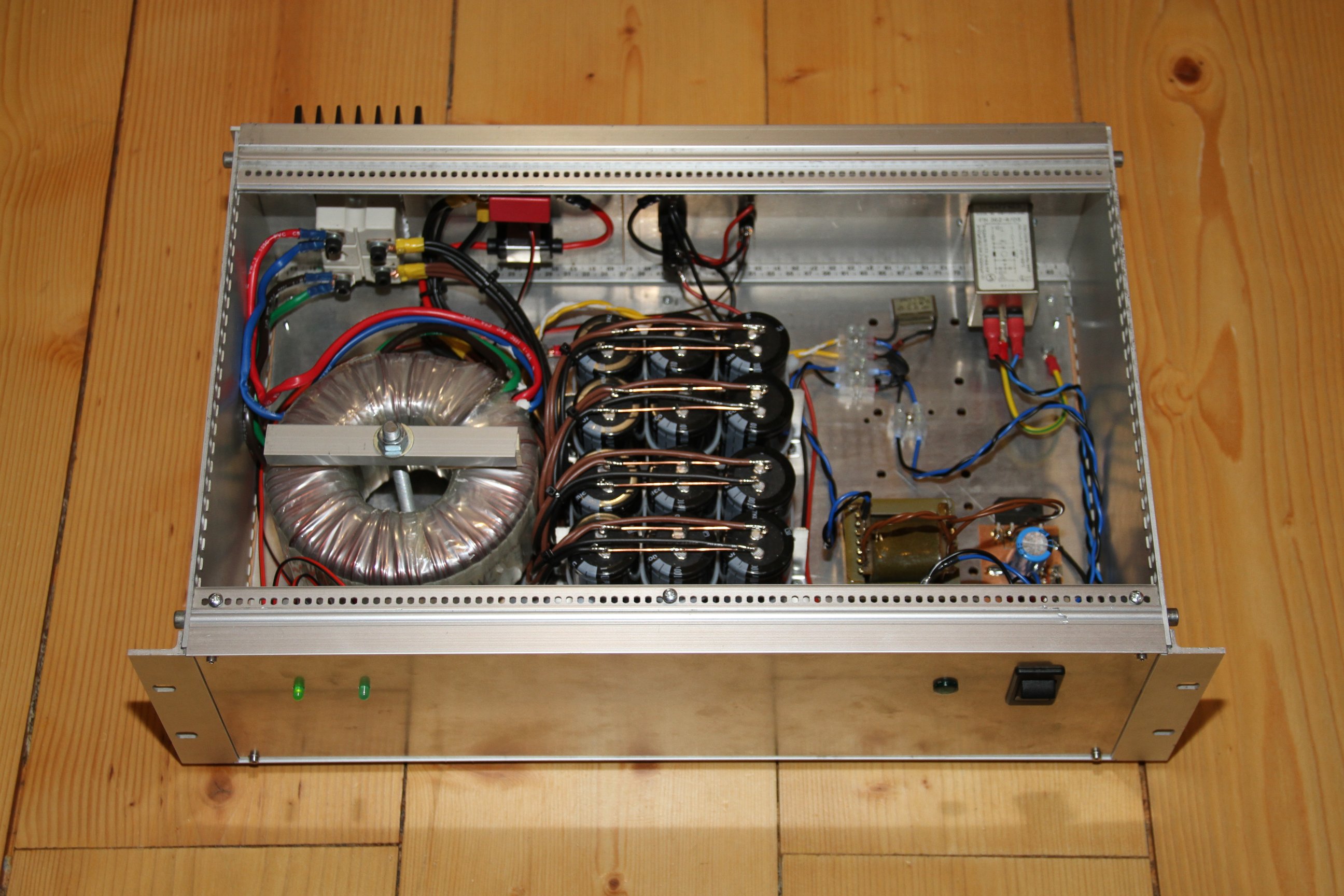
Power supply unit, front view (click to enlarge).
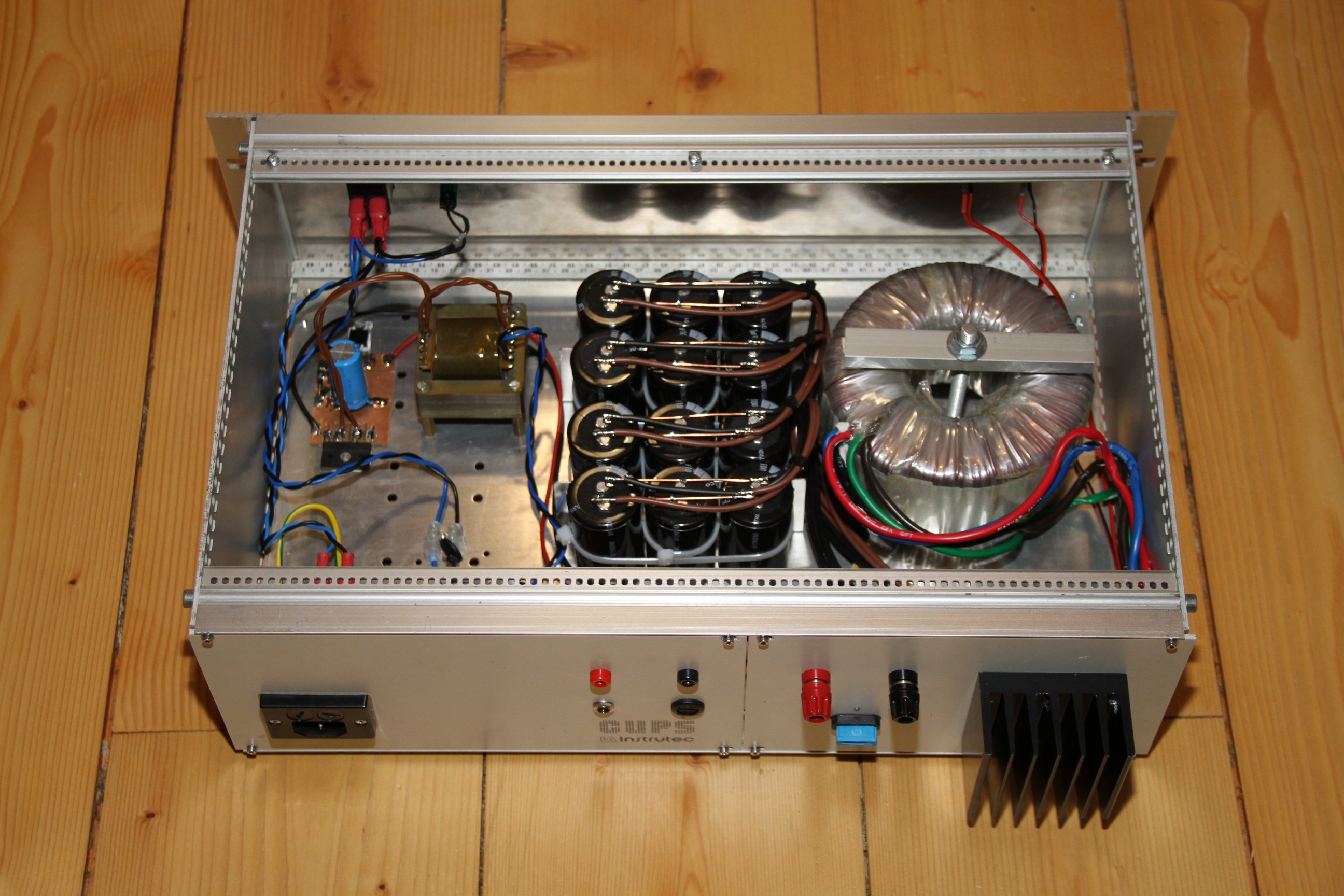
Power supply unit, back view (click to enlarge).
| Home | Electronics | Index | Previous page | Next page |