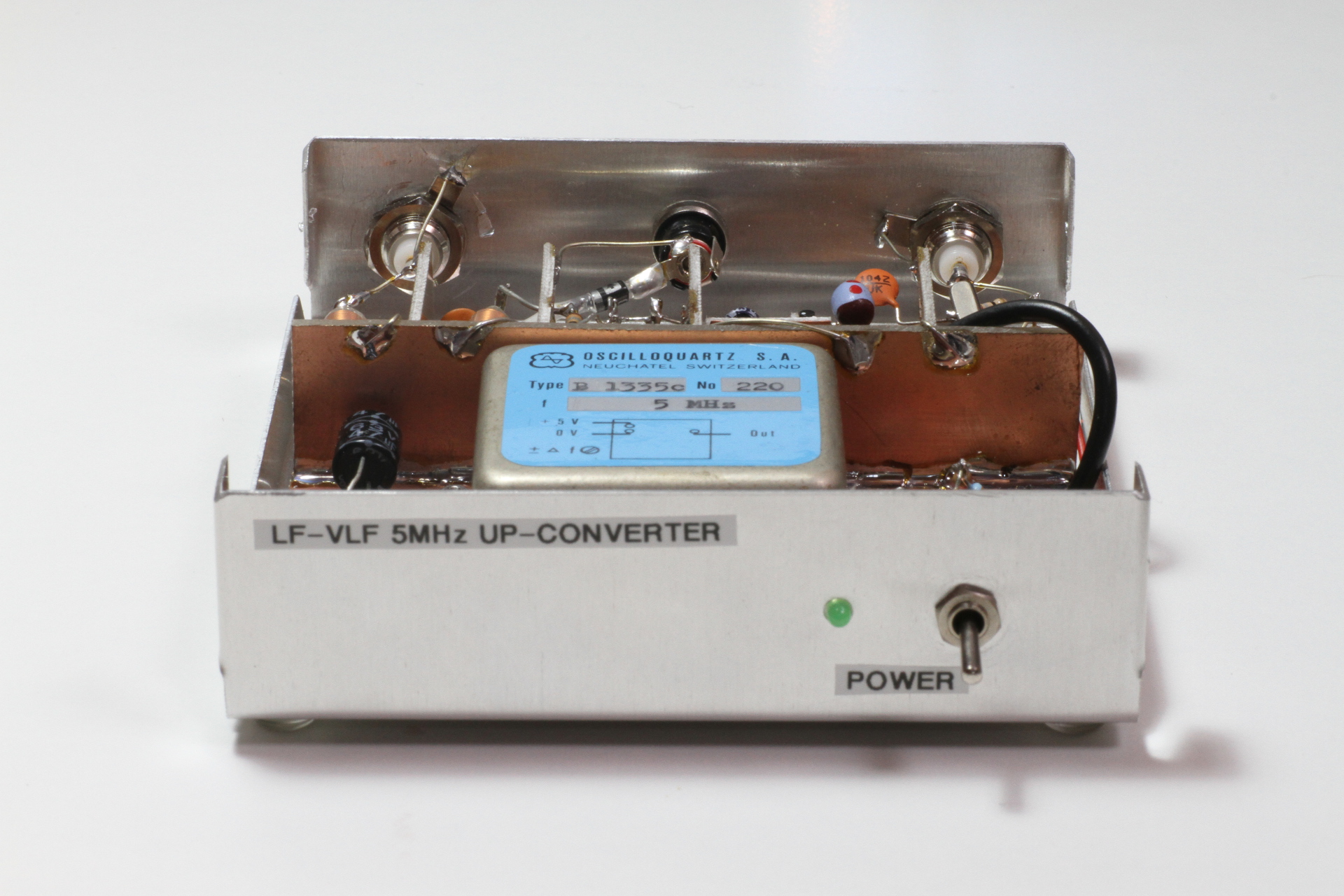
Front view of the finished up-converter.
Listening to very long waves (VLF) is fascinating with lots of interesting signal to hear, like the historical Swedish transmitter SAQ on 17.2 kHz or the famous German time station DCF77 on 77.5 kHz.
Unfortunately, radio receivers covering this band are very rare. Some amateur radio transceivers can tune down to 100 kHz, some others down to 30 or even 20 kHz, but sensitivity (or overall performance) is often disappointing and the vast majority of radio receivers are just not suitable for VLF. For receiving below 20 kHz, some people connect their antenna directly (or with some simple circuit) to the microphone input of their PC soundcard and use software to tune in the desired signal. Personally, I prefer up-converting the low frequency band and feed it to a regular shortwaves amateur radio receiver, so that I can use all the nice filtering and noise reduction features I'm used to. This has also the advantage of allowing a wider band, say from 0 to 500 kHz as is the case of the circuit described here.
Front view of the finished up-converter.
I already built such an up-converter many years ago, in the early nineties. It was based on the famous integrated circuit mixer S042P and came from a project published on a famous Italian electronics magazine of that era. Even if this circuit worked and allowed me many happy receiving experiences, I was never really fully satisfied: it was noisy, the suppression of the local oscillator was bad, the frequency was inaccurate and, for several reasons, it could not go below a few kHz.
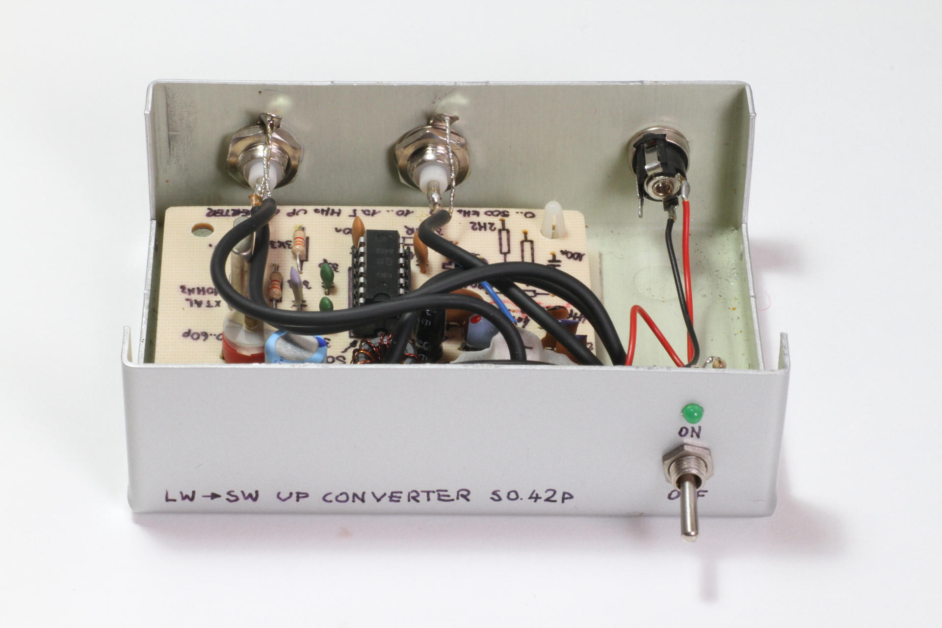
Picture of the old up-converter, built in the early nineties.
There are many similar up-converters around: one can easily find plenty of circuits on the internet or on many radio magazines, but I couldn't find one that matches my expectations. So, after hesitating for several years, I decided to design a new one, trying to improve the weakness of the old one. As usual, engineering is a matter of choosing a compromise and the converter described here is not perfect either. But I tried to describe all the pros and cons of all the technical choices that have been made here, so that you can reconsider them in order to meet your own criteria.
First, I wanted to tune almost down to 0 Hz, or at least very close. This has two implications: the local oscillator must have a very low phase noise and the input circuit (until and including the mixer) should be DC coupled (no series capacitors or transformers). DC coupling the antenna has some disadvantages: for example any DC potential on the antenna will upset the mixer and reduce performance preventing the use of any bias-T to power a preamplifier. Then, no balun can be used because they don't work down to DC, and this prevents using any mixer requiring a balanced input. DC-coupling the antenna also prevents from directly using any Gilbert-cell mixer because of the DC bias required on their input that the antenna may short to ground. Any passive antenna should be used with this converter, no matter if insulated or with a DC connection to ground.
The circuit is composed by three blocks around the mixer: the input circuit that feeds the signal coming from the antenna to the mixer, the output circuit that feeds the signal from to mixer to the radio receiver and the local oscillator circuit that drives the mixer.
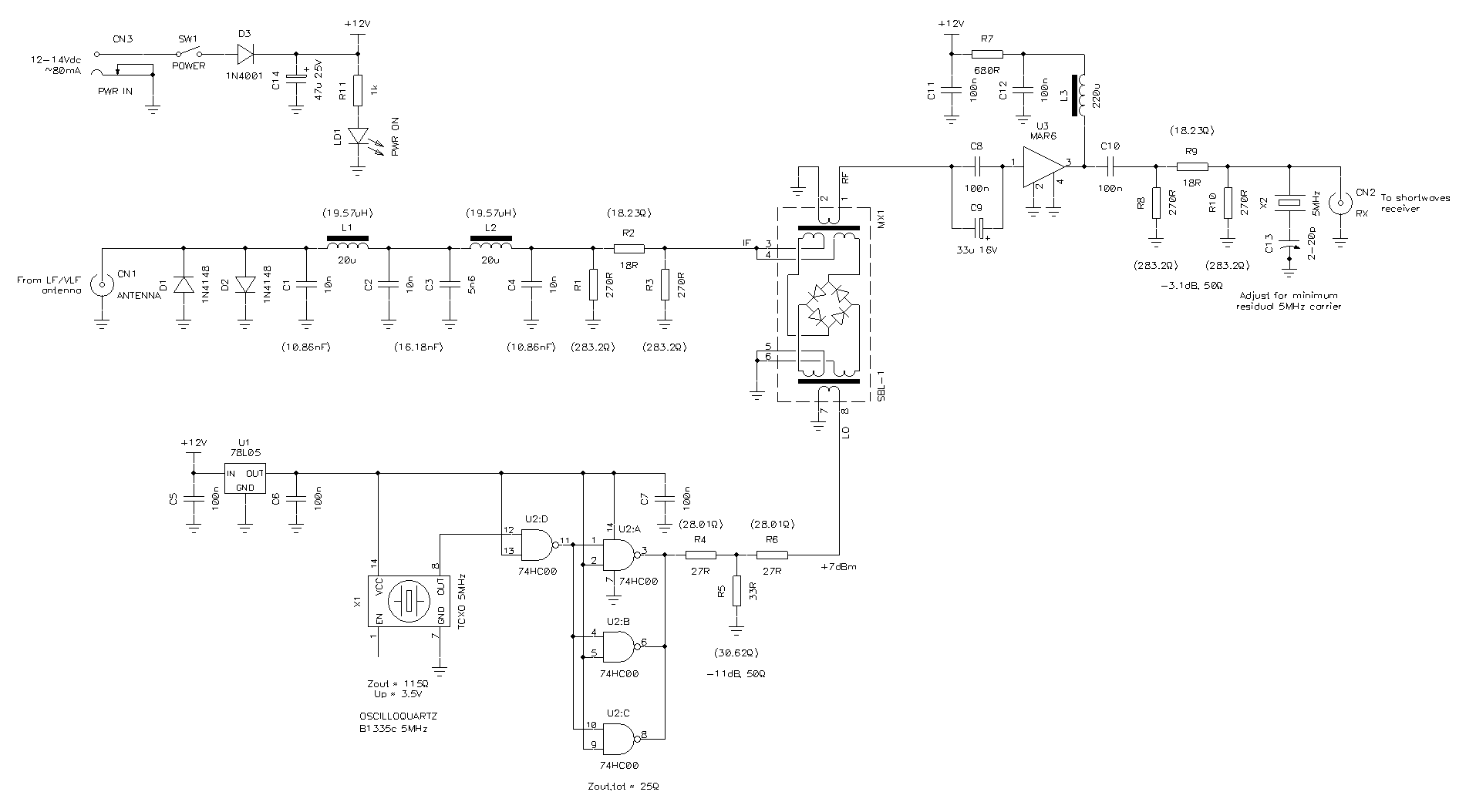
Block diagram (click for full diagram).
The mixer is in the the center in yellow,
the input block is on the left in cyan,
the local oscillator block is at the bottom in red,
the output block is on the right in blue and
the power supply block is on the top left in green.
PDF version of the schematic diagram: lwupconv.pdf (49,469 bytes).
Here, MX1 is a MiniCircuits double balanced mixer type SBL-1: it's quite common and easy to find, has good performance, good carrier suppression, low noise, single ended ports (no balun required) and has a port that can go down to DC. But it's a passive device based on a diode ring and has the disadvantage of a conversion loss of about 6 dB. This loss actually worsens the signal-to-noise ratio of the incoming signal by the same amount (actually about 10 dB, see below), but I decided that this was fine for me. A Gilbert cell mixer (like the S042P) would have a conversion gain, but would also add noise due to the internal transistors and at the end the signal to noise ratio will be worsen anyway, not to mention that it will would be much more difficult to extend the input bandwidth down to 0 Hz.
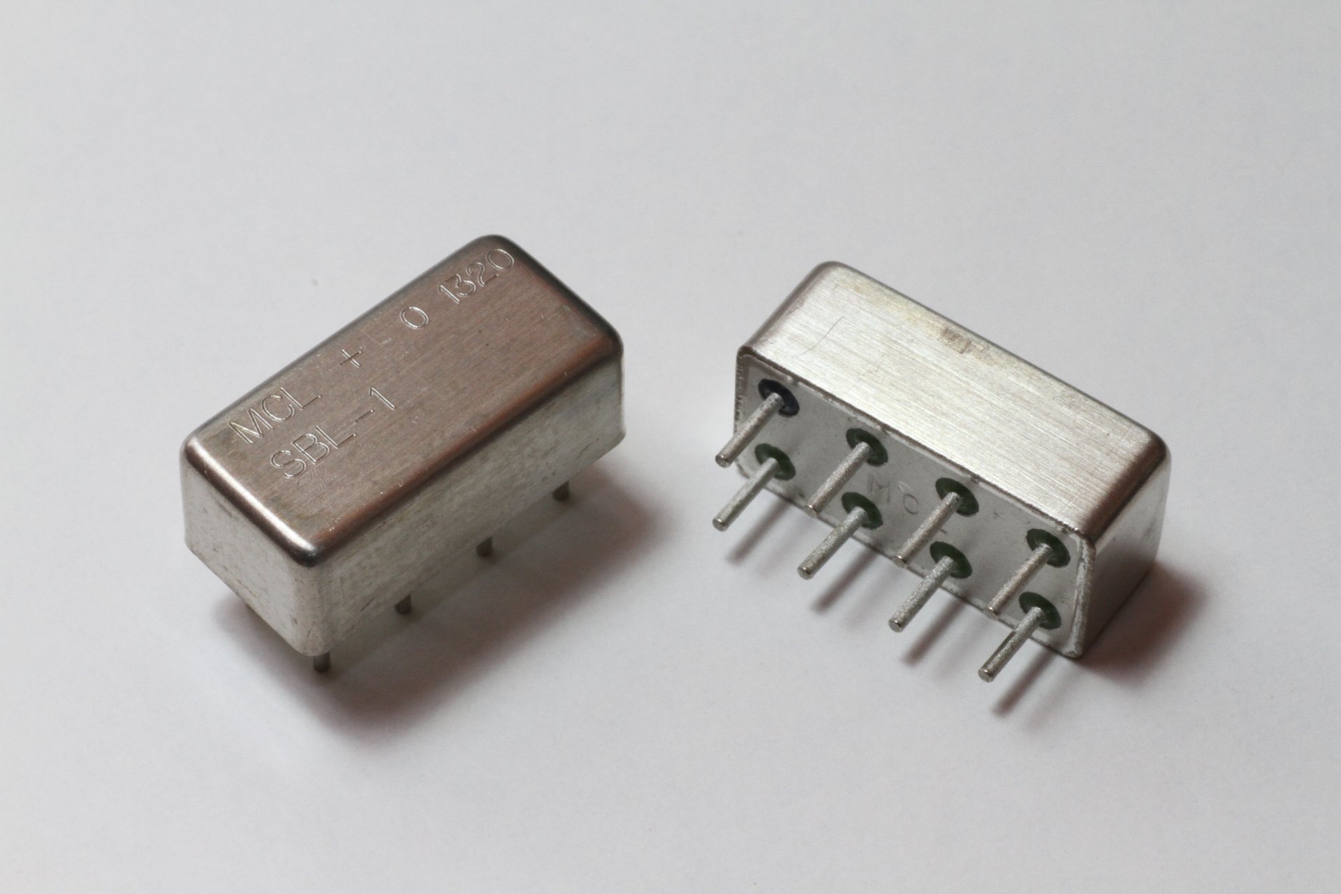
Picture of two MiniCircuits SBL-1 mixers.
Let's have a look first at the input circuit: the antenna is connected to CN1 and the two 1N4148 diodes D1 and D2 protect (within reason) the converter from small surges. Diodes, like all non-linear devices, add distortion and cause intermodulation. Here, the amplitude coming from the antenna is supposed to be small and the effect of the diodes can be neglected. Of course, you could choose to skip the diodes and accept the increased risk of damaging the mixer in case of surge or strong signal (received, for example, by the antenna while operating a transmitter nearby). According to the specs, the SBL-1 will not survive more than 50 mW (17 dBm) or 40 mA DC. The diodes will keep the power delivered to the mixer below 10 mW (10 dBm) or 14 mA while tolerating 500 mW (27 dBm) or 150 mA for short periods of time.
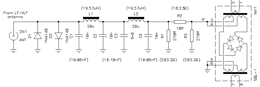
Circuit diagram of the input block.
Then, C1, L1, C2, C3, L2 and C4 form a 5th order Tchebysheff low-pass filter with a cutoff frequency of 500 kHz, a pass-band ripple of 0.5 dB and a characteristic impedance of 50 Ω. Its role is to prevent signals of unwanted frequencies to reach the mixer, because they may fall in the desired band when converted. The cutoff frequency must be less than half than the one of the local oscillator, but it's better to have some margin to allow the filter to roll off. Here, the value of 500 kHz has been chosen and makes a good compromise between having a large coverage and letting in too many strong signals causing intermodulation. This value allows converting all the very long and long waves where many available receivers are poor performers, but cuts medium waves, short waves and higher frequencies, where very strong signals from local transmitters may be problematic. You may want to change the cutoff frequency to fit your specific needs, but removing the filter to skip the 0.5 to 1 dB insertion loss is a bad idea.
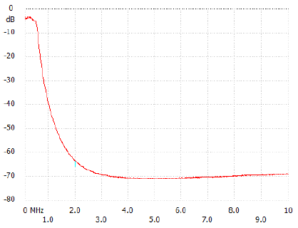
Input filter transfer function from 0 to 10 MHz.
Please remark the good stop-band performance (about 70 dB) and the
insertion loss of about 4 dB in the pass-band, mainly due to the
attenuator.
Before entering the mixer, there is a 3.1 dB attenuator composed by R1, R2 and R3. The need of this attenuator is somehow questionable because its attenuation adds up to the conversion loss of the mixer and the insertion loss of the low-pass filter to about 10 dB degrading the signal-to-noise ratio by the same amount, but has the advantage of showing an impedance close to 50 Ω to both input filter and mixer. This is because mixers love to see a matched 50 Ω impedance on all ports at all frequencies involved in the conversion; this means down to DC in this case. If this is not the case, the mixer still works, but its performance in terms of intermodulation and image suppression is degraded. Then, the low-pass filter also likes to see a 50 Ω impedance at its output to work properly. Finally, the antenna has little chances to have a good a good match to 50 Ω at such low frequencies upsetting the mixer anyway. The attenuator also adds extra protection for the mixer by letting through only half of the power and discharging to ground any static charges that may accumulate on an insulated antenna on a dry and windy day. For these reasons, this 3.1 dB attenuator is included in the design. If you don't care about mixer performance and extra protection, you can skip it.
After the attenuator the signal enters the SBL-1 mixer through the IF port. This is somehow unusual, because normally the antenna is connected to the RF port. Here this is not possible because the RF port connects internally to a transformer that cannot go below 500 kHz. The only port capable of going down to 0 Hz is the IF port that internally connects directly to the diode ring, and it's ok to feed the signal from the antenna to this port because passive diode mixers work in both ways. Impedance matching on all mixer ports is important, because being bidirectional, any spurious signal reflected by a mismatch will go back in the mixer and converted again degrading performance.
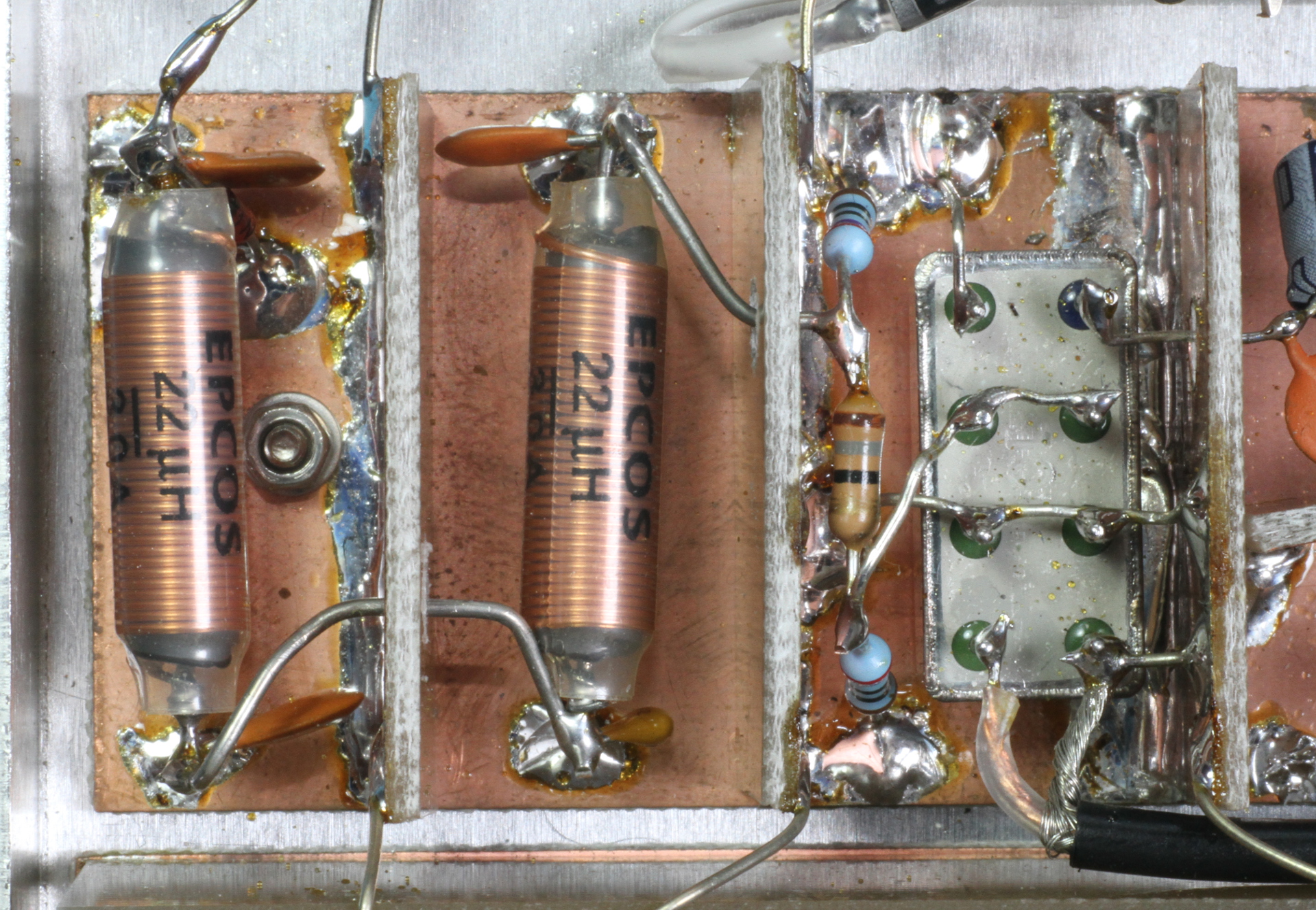
Picture of the input circuit (left) and the mixer (right).
A good local oscillator is mandatory. Don't even think about using LC oscillators, you need at least a crystal oscillator, but a good crystal oscillator is even better. The lower the frequency you want to tune, the better the oscillator you need. First, it's very handy to have a round MHz frequency, so that you can read the actual frequency simply by ignoring the MHz and reading only the kHz. For example, suppose you are listening to SAQ radio station on 17 200 Hz and that the local oscillator is 5 000 000 Hz nominal like the one I selected here. With the converter, you should tune your radio to 5 017 200 Hz (5 MHz + 17.2 kHz). Just ignore the first "5" and read the rest. If you selected a 4 433 619 Hz crystal instead, you would tune the same station on 4 450 819 Hz and you would need a calculator to figure out what you are doing.
Any frequency from 2 to 30 MHz will do the job with this circuit: I found a good 5 MHz TCXO (Temperature Compensated crystal Oscillator) in my junk-box so I used 5 MHz, but you may have a different frequency. Just make sure the selected frequency falls in a band your favorite receiver can tune (with good sensitivity) and that is much more than twice the input low-pass filter cutoff frequency (this is why you shouldn't go below 2 MHz). Frequencies above 30 MHz can be used, but U2 (a 74HC00) will not follow and a different circuit should be used. But there is little interest in using higher frequencies because the vast majority of good amateur radio receivers cover from 1.8 to 30 MHz with the required performance (like narrow-band CW, good sensitivity and so on).
The accuracy and stability of the frequency is important when tuning the VLF band. Imagine that your local oscillator is +20 ppm off, and 20 ppm is a typical accuracy of and ordinary quartz crystal. So, the local oscillator is actually at 5 000 100 Hz instead of 5 000 000 Hz and your station will be converted to 5 017 300 Hz. Now, if you read 17.3 kHz instead of 17.2 kHz, you have a 5 800 ppm error, which I consider annoying. So it's important to use a very precise crystal or to have a way of fine tuning its frequency to compensate for errors. For this reason, regular (and cheap) "microprocessor type" crystal oscillators, in their metallic DIP-14 housing are not very good because of their 20 to 50 ppm accuracy and the lack of frequency adjustment screw.
Oscillator stability and phase noise is very important for the lowest part of the band. If you want to tune closer and closer to 0 Hz, you will actually tune closer and closer to 5 MHz. Phase noise increases as you get very close to the oscillator frequency and weak signals will be draught in the phase noise. The lowest the phase noise of your oscillator the better is your converter.
I used a TCXO because it has low phase noise and because its frequency is stable with temperature. It also has a little adjustment screw to fine tune the frequency. But if you don't care about frequency accuracy and you aren't interested in tuning below a few kHz, you can just use any crystal oscillator you have on hand.
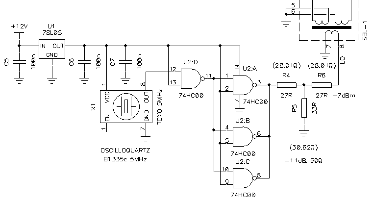
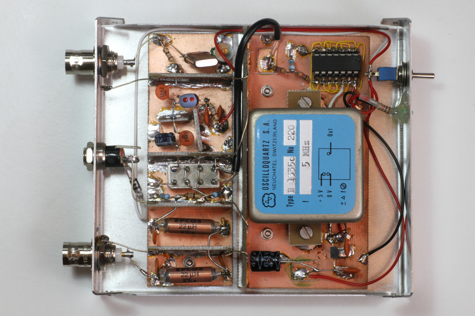
Circuit diagram of the local oscillator block.
The TCXO and the buffer circuit U2 (and many other crystal oscillators as well), require a regulated 5 V power supply and this is provided by U1, a classic 78L05. Here the TCXO is an Oscilloquartz B1335c at 5 MHz. It has a ±0.5 ppm stability between 0 and 60 °C, plus ±0.5 ppm aging per year; phase noise is below –80 dBc at 10 Hz dropping at –110 dBc at 100 Hz. The square wave signal provided by this oscillator (X1) is unfortunately a bit weak and the output impedance is a bit too high to match the requirements of the mixer. Therefore U2 is used as a buffer to amplify the signal and lower its impedance. The attenuator composed by R4, R5 and R6 is used to reduce the amplitude by 11 dB and feed the mixer with 7 dBm on its LO port as required, while perfectly matching the impedance to 50 Ω. If your oscillator provides already a strong output signal, you can skip U2, but you may need to recalculate the attenuator to provide 7 dBm.
Ring mixers also work (sometimes slightly better) with a square wave local oscillator, so there is no need to add a filter here to cut the harmonics. But if your oscillator already provides a nice sine wave, the circuit will work fine as well.
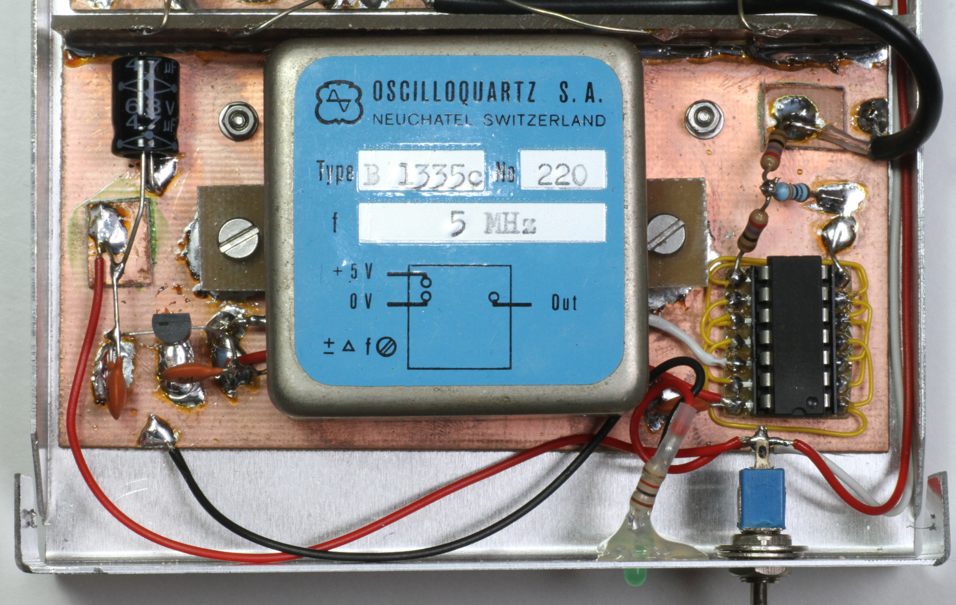
Picture of the TCXO (middle) with its 5 VDC power
supply (left) and buffer circuit (right).
The converted signal emerges at the RF port and could be fed theoretically directly in the antenna connector of your radio receiver. But there are some downsides: first, many radio receivers (except professional equipment) do not always have a matched 50 Ω impedance on their antenna input and the mixer could not like its load. Another 3 dB attenuator here would do the job nicely, but I didn't want to lose extra signal, so I decided to go for an amplifier for both matching the impedance and compensate for the losses.
The choice of the amplifier is not an easy one, because it has to show a nice and constant 50 Ω impedance on its input at all frequencies (from almost DC up to many MHz above the concerned band). The first idea was to use high speed operational amplifiers and keep the DC coupling, but the complexity (and cost) of the circuit was too high. I also discarded the idea of using a single transistor because it was quite complicated to match the impedance on such a broad band. I finally used an MMIC because it's easy to implement, has nice constant impedance on both input and output, has high gain and low noise, and is unconditionally stable.
I selected the popular a Mini-Circuits MAR-6 MMIC amplifier, because it's easy to find, cheap, has good performance and its input impedance is guaranteed matched down to DC. Unfortunately, it's not possible to DC couple it to the mixer, because it has some internal DC bias on its input, so I used two capacitors in parallel (C8 and C9), a ceramic one of 100 nF for coupling the RF and an electrolytic one of 33 μF for coupling low frequencies down to 100 Hz.
Now, one should keep in mind that the main signal going out from the mixer is between 500 kHz above and below 5 MHz (according to the choice of input filter and local oscillator), but we want to match the impedance down close to 0 Hz to avoid spurious signals from being reflected back into the mixer degrading its intermodulation performance. If you don't care about it, you can skip the extra electrolytic capacitor.
The MAR-6 has a gain of 22 dB, a noise figure of 3 dB and an IP3 of +14.5 dBm, enough to compensate for the losses of the previous blocks and add even more gain. Unfortunately, the signal to noise ratio degraded by the previous attenuation cannot be recovered, but this is part of the design choices and has to be accepted.
Circuit diagram of the output block.
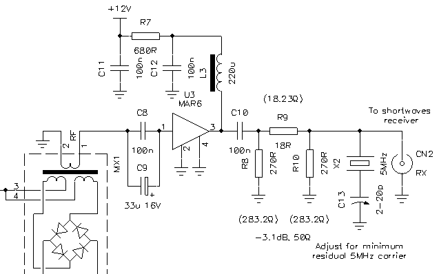
The MMIC (U3) is powered via a 560 Ω bias resistor R7 connected to its output. Inductor L3 isolates this resistor that would otherwise be in parallel with the output at RF degrading its performance. The two 100 nF bypass capacitors C11 and C12 make sure the power supply rail is grounded at RF and that no signal leaks (in or out) via the power supply cable. At the amplifier output, we don't care anymore about matching low frequencies and a single 100 nF coupling capacitor C10 is enough.
The SBL-1 mixer does a good job in suppressing the carrier (the local oscillator signal) and its isolation is specified around 60 dB, but the LO at +7 dB will emerge on the RF port at –53 dBm, still a strong signal. So, at the output of the amplifier, I included a notch filter composed by a 5 MHz crystal X2 in series with a 2-20 pF trimmer capacitor C13. The goal of this filter is to further attenuate this signal by some extra 20-30 dB so that your receiver will not saturate (or upset the AGC circuit) when trying to tune close to 5 MHz. This filter is placed after the amplifier so that its unmatched impedance will not be seen by the mixer. Again, if you don't care tuning very low frequencies, you can skip this filter.
To tune this notch filter, tune your receiver to the frequency of the local oscillator (5 MHz) and gently rotate the adjustment screw of C13 with a plastic screwdriver for the minimum possible received signal.
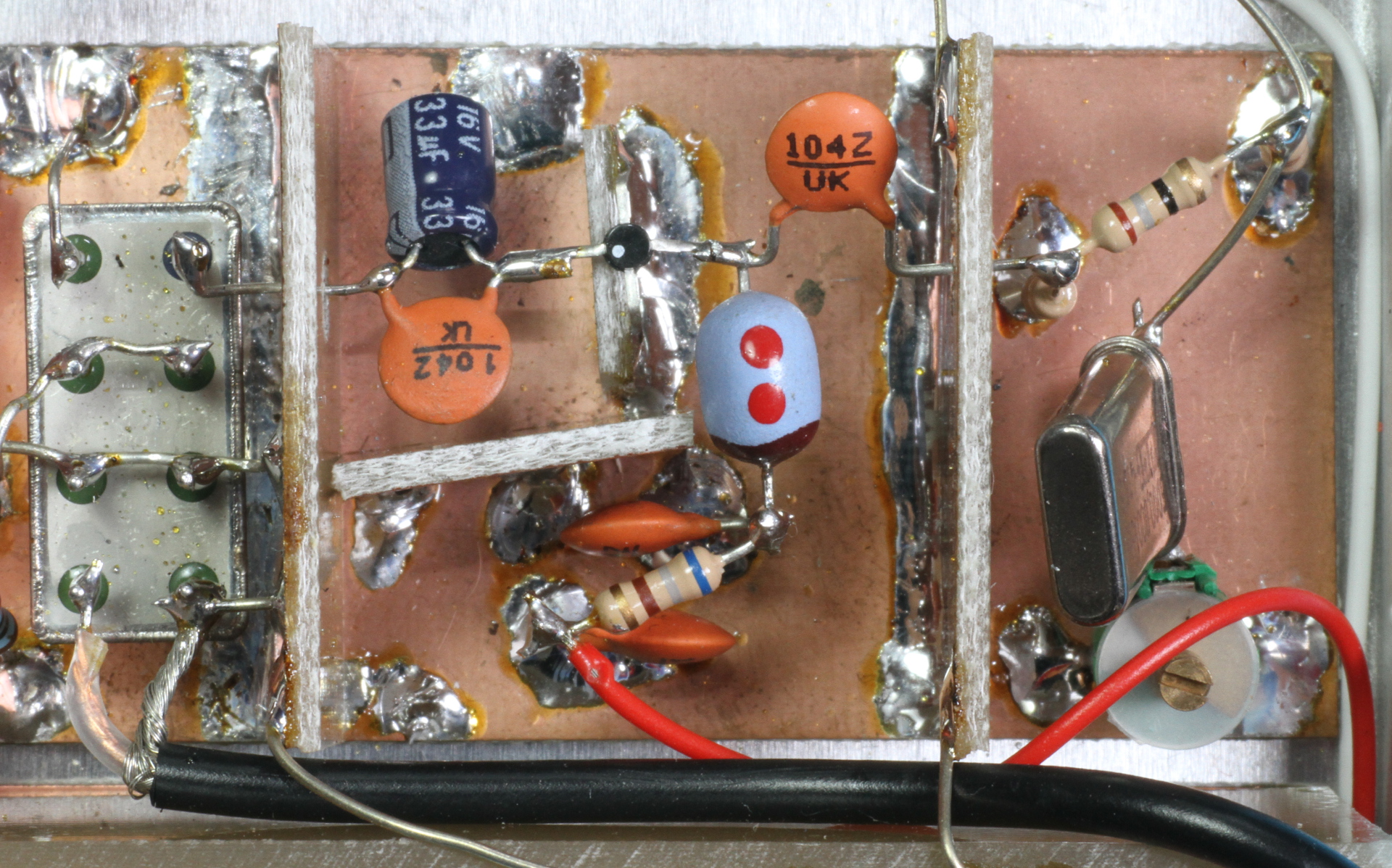
Picture of the mixer (left) and the output circuit (middle) with the
quartz filter (right).
Finally I added a last 3.1 dB attenuator composed by R8, R9 and R10 to match the output impedance and protect the MMIC from small surges that may appear when connecting or disconnecting the output cable.
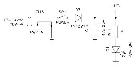
Circuit diagram of the power supply block.
I think that the power switch SW1, power on LED LD1 and polarity protection diode D3 do not need any extra comment. The converter is supposed to be powered with a 13.8 VDC power supply and requires about 80 mA.
For RF circuits, I often solder components directly on a copper plated FR-4 board without designing and etching any PCB. This technique is simple, has good RF performance and allows easily playing and modifying until the desire result is achieved. It's also very easy to add screens between the different blocks to minimize stray coupling. Here we talk about MHz, so we don't need full enclosures, and small metal plates (or FR-4 copper boards) in-between the different blocks are enough.
I probably added more screens than necessary, but there are a few ones that have good reasons to be there. The screen between the two inductors of the input low-pass filter is very important: if omitted, the attenuation in the stop-band will hardly be better than 30 dB while with just a little piece of copper it can go well above 60 dB! Another important screen is the one that hides the local oscillator with its strong 5 MHz signal so that you have less to fight with the final crystal notch filter. I also used coaxial cables to feed the mixer to minimize 5 MHz stray coupling. Finally, when you have an amplifier, you never want stray coupling between its input and its output, so you add at least one screen to keep them apart (here, for example, you don't want the output connector in close proximity of the amplifier input).
Top view of the finished up-converter.
Finally, I mounted the whole converter in a metallic enclosure to completely shield it and have a nice and good looking device.
If you don't already have a good quality antenna for LF and VLF, you can start with a long piece of wire, insulated from ground and hanged as high as possible. For very long waves you need a very long wire: a few dozen meters being the minimum; the longer the wire, the stronger the signal. The actual layout of the wire is not very important: to get started, it doesn't matter if your antenna is straight, bended or in zigzag shape; just hang as much copper as possible as high as possible.
Since this is a receiving antenna, the voltage is very low there are no insulation problems, so you don't need to use ceramic insulators or a special kind of wire. Just hang a regular PVC insulated single wire of any size up on some trees and connect it to the central connector of the converter input. Than make sure the outer ring of the input connector is connected to a good ground and you're ready to start.
There are many low frequency antenna designs that deserve some experimenting, like magnetic loops (horizontal and vertical), beverages, long wires laying directly on the ground, and so on. The ground connection also plays an important role being often part of the antenna.
A simple but performing LF and VLF up-converter has been presented and described in detail, hoping this helps in finding the right compromise according to everyone's specific needs. Its construction is not too difficult and the required materials can be found in the usual junk-box. It allows exploring a very interesting band where I spent many happy hours in spotting a lot of weak and mysterious signals well below 20 kHz.
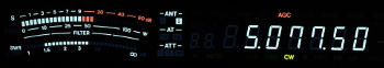
Received DCF-77 signal from the Mainflingen Longwave Transmitter on
77.5 kHz (it has an ERP of 30 kW and is about 400 km
away.
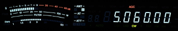
Received MSF signal from the Anthorn Radio Station on 60 kHz (it
has an ERP of 17 kW and is about 1'200 km away.
| Home | Electronics | Page hits: 049099 | Created: 08.2014 | Last update: 08.2014 |