Thermal equivalent circuit example described in the text.
When designing low power electronic circuits, thermal calculation can often be neglected, but if the circuit deals with more power like in a power amplifier or in a power supply, a thermal evaluation is a must.
If the power transistors (and power components) are not cooled correctly they will overheat and generally blow up in a few minutes (or even a few seconds).
Evaluating the power that is dissipated in power transistors is a long and complex story that depends on circuit configuration and circuit working mode (bias point, duty cycle, frequency,...). But here we suppose this information is known. If not, one can still try to guess it, knowing for example the efficiency of the circuit or applying Joule's law (P = U·I) on the supposed component voltage and current.
At the end a test phase while monitoring all temperatures for a few hours is a very good idea: any error or wrong estimation in the thermal calculation can easily be spotted and fixed.
The old rule of thumb "if you can hold your hand on it, it's not too hot" still applies nicely; the opposite is not necessarily true (a transistor at 80°C is too hot to touch but can work ok). In any case, it's a bad idea to have very hot components because you could get hurt if you accidentally touch them. If you have to, you'll have to add some protections like grids or enclosures to avoid accidental contacts. And cool components have a longer lifetime than hot ones.
The heat flows spontaneously and naturally from a hot body to a cold one, by conduction, by convection, by radiation or by a combination of the three. The amount of heat flowing is roughly proportional to the temperature difference between the two bodies and inversely proportional to the so-called "thermal resistance" that is a propriety of the material in-between the two bodies. Materials with high thermal resistance are called thermal insulators (wood, mineral wool and many plastics are good thermal insulators) and materials with low thermal resistance are called thermal conductors (copper and aluminium are very good thermal conductors).
The analogy with Ohm's low is straightforward. In Ohm's law, a current flow is proportional to a voltage difference and inversely proportional to an electrical resistance. We can therefore use the following substitution:
| Electrical | Thermal |
| Voltage (potential difference) [V] |
Temperature difference [K] or [°C] |
| Current [A] |
Heat flow (power) [J/s] = [W] |
| Electrical resistance [Ω] = [V/A] |
Thermal resistance [K/W] or [°C/W] |
Heat is measured in Joules and heat flow in Joules per second, which is also the dimension of power (1 W = 1 J / 1 s). So the heat flow is nothing more than the thermal power being transferred.
Thermal resistance usually is expressed in K/W or in °C/W. Since it's based on a temperature difference and not on the absolute temperature, both units are perfectly equivalent, meaning that, for example, 3.5 K/W ≡ 3.5 °C/W. In this page °C/W are used because temperatures are also expressed in °C, but K/W would be exactly the same.
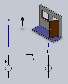
Let's take an example: we have a component dissipating a power of 10 W. The thermal resistance between the component and the ambient is 2 °C/W. The ambient temperature is 25 °C. We want to know the temperature of the component. In our equivalent circuit, the power dissipated by our component is represented by a "current" source forcing a flow of 10 W. The thermal resistance is represented by a "resistance" of 2 °C/W and the ambient temperature is represented by a "voltage" source of 25 °C. Ground potential is assumed to be 0 °C, but this value is not important, because everything is based on temperature differences and it never appears in calculations. This circuit is shown in the picture below:
Thermal equivalent circuit example described in the text.
We can easily figure out that 10 W flowing in a thermal resistance of 2 °C/W generate a temperature rise of 10 W · 2 °C/W = 20 °C. This temperature is added to the ambient temperature and we find 20 °C + 25 °C = 45 °C and this is the temperature we are looking for. There is nothing more than Ohm's low and the equations are really easy.
This very simple model is enough for designing most of the heat sinks used in electronics: it computes the steady state of the thermal circuit, or in other words, the status of the system after a long time of operation. One could also model heat capacity by adding equivalent capacitors between each (relevant) node and the "thermal" ground. This would allow computing the thermal response as a function of time to see how heat pulses average out, but would be beyond the possibility of the calculators in this page; you would need to do some "pencil and paper" work or use and analog circuit simulator.
Sometimes the dissipation of a component alone is enough and no heat sink is required. And some components are not designed to be mounted on a heat sink at all. But if the power to dissipate is significant compared to the size of the component, a thermal evaluation should be done in any case.
In this case the thermal circuit is very simple and is represented in the diagram below:
Equivalent thermal circuit without heat sink.
The following calculator will do the math for you, just enter 3 out of the 4 values leaving the unknown one blank. Than hit the "calculate" button to calculate and fill in the missing value.
For higher power dissipations, a heat sink is required. The equivalent thermal circuit is a bit more complex, but still very simple, as one can see in the figure below:
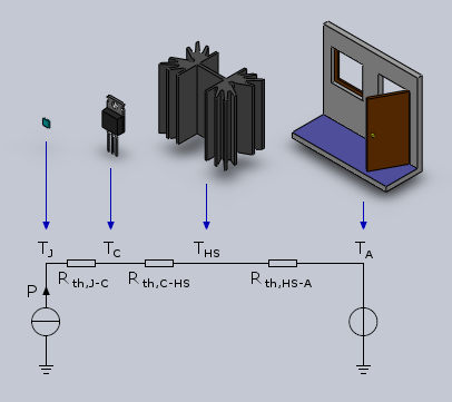
Equivalent thermal circuit with heat sink.
Here we have more variables to deal with and we may need to have more than one unknown. Enter all the known data in the calculator below and leave blank the fields to calculate, than click the "calculate" button to compute and fill in the blanks. Not all combinations are possible; if not enough data is available; a pop-up box will warn you. Make sure the unknown fields are completely empty: a space character will not work.
The forced airflow factor F takes into account an optional blower that will force cool air through the fins of the heat sink (see below). Set F to 1 if a blower is not used.
In components datasheets you usually find all the necessary data about thermal design. Sometimes, the datasheet is not available, so the following table can be handy for an approximate estimation of the necessary parameters according to the transistor (or IC) case.
Some transistors have better thermal characteristics than others even if they have the same case, but the order of magnitude is the same. Having an idea of the expected thermal characteristics of a component also helps in spotting errors in the calculations or in the datasheets. If in doubt, choose a higher thermal resistance and a lower junction temperature.
| Case | Picture | Rth,J-C [°C/W] |
Rth,J-A [°C/W] |
Ptot @ TA [W] |
Ptot @ TC [W] |
TJ [°C] |
Example |
| DO-27 DO-201AD |
 |
15...50 | 6 | 150 | 1N5401 | ||
| DO-35 DO-204AH |
 |
250-300 | 350 | 0.5...1.15 | 0.2...0.4 | 125...200 | 1N4148 |
| DO-41 DO-204AL |
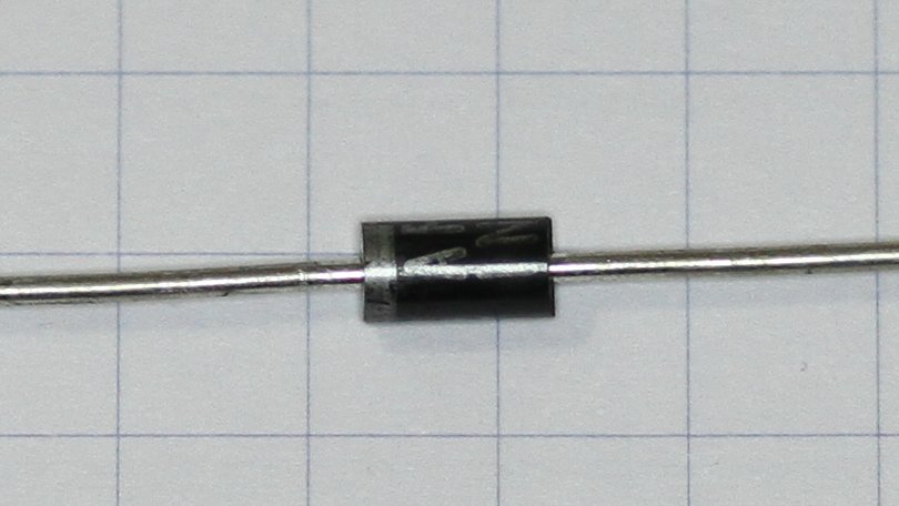 |
25 | 50 | 175 | 1N4007 | ||
| TO-3 | 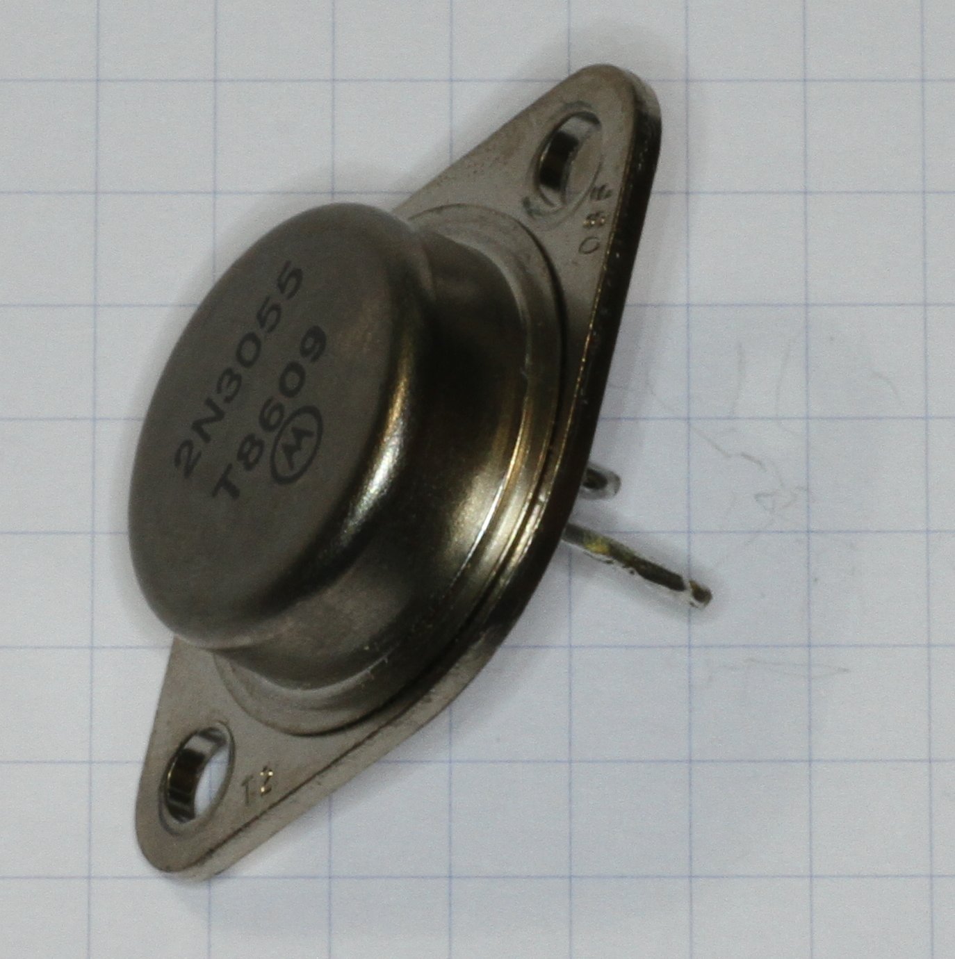 |
1.5 | 30...40 | 115 | 200 | 2N3055 | |
| TO-3P | 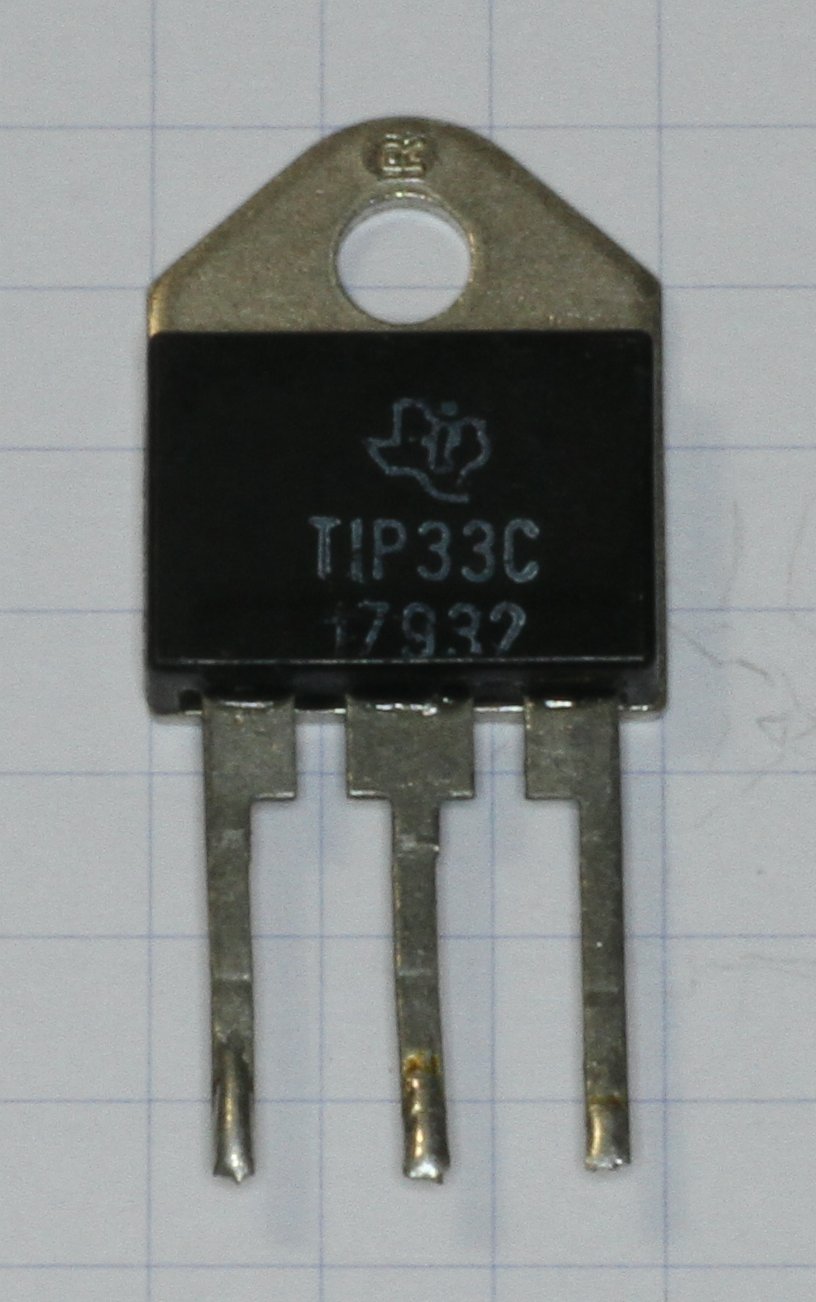 |
1...2.8 | 35...50 | 45...150 | 150...175 | TIP33C | |
| TO-18 | 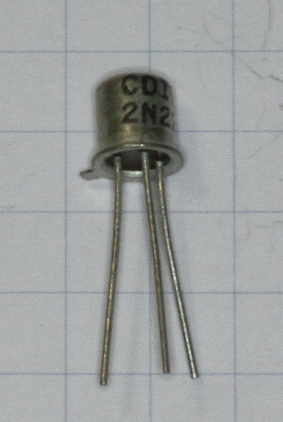 |
80...200 | 300...500 | 0.7...1.8 | 0.3...0.6 | 150...200 | 2N2222 |
| TO-5 TO-39 |
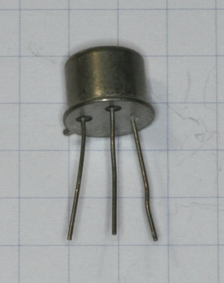 |
58 | 200...300 | 3 | 0.6...0.8 | 200 | 2N2905 |
| TO-92 | 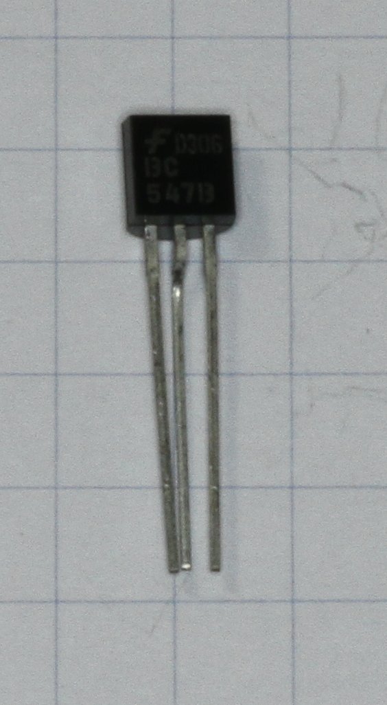 |
75...125 | 125...360 | 1 | 0.3...1 | 150 | BC547 |
| TO-126 TO-225AA SOT-32 |
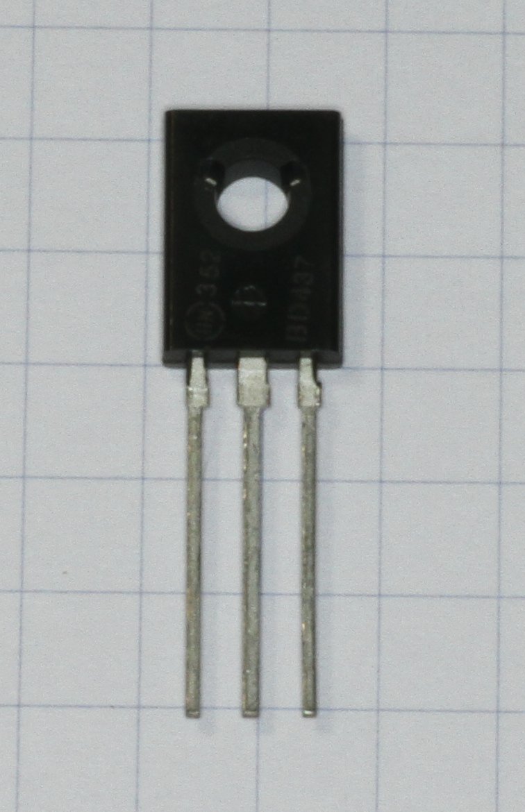 |
3.5...10 | 80...100 | 12...36 | 1.1...1.3 | 150 | BD437 |
| TO-220 | 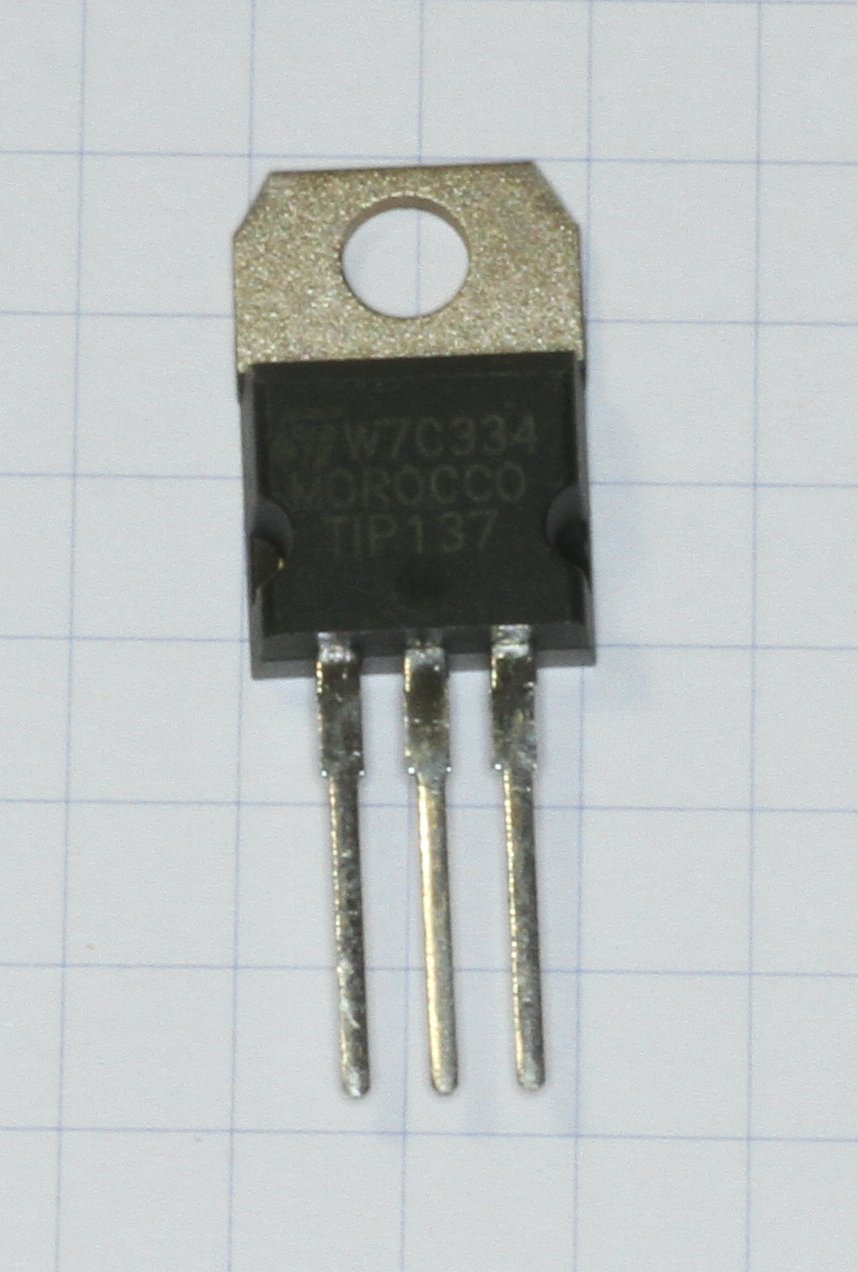 |
1.7...8 | 55...70 | 65...70 | 2 | 125...150 | TIP137 |
| DIP-8 | 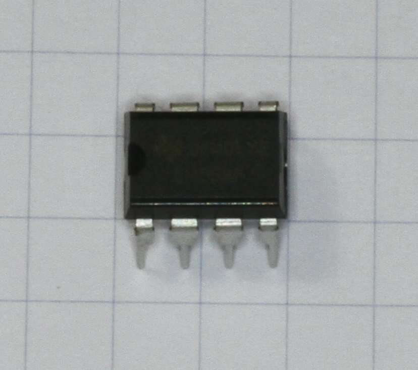 |
37...40 | 85...110 | 0.2...1.25 | 150 | LM358 | |
| SOT-23 TO-236 |
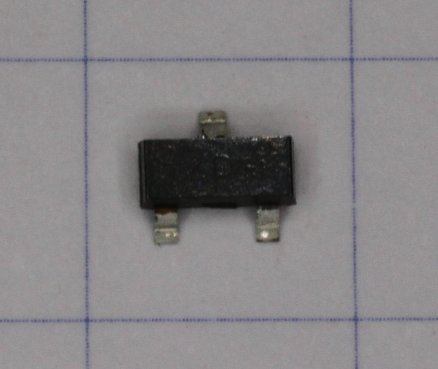 |
430...560 | 0.22...0.35 | 150 | BC847 | ||
| SOT-143 | 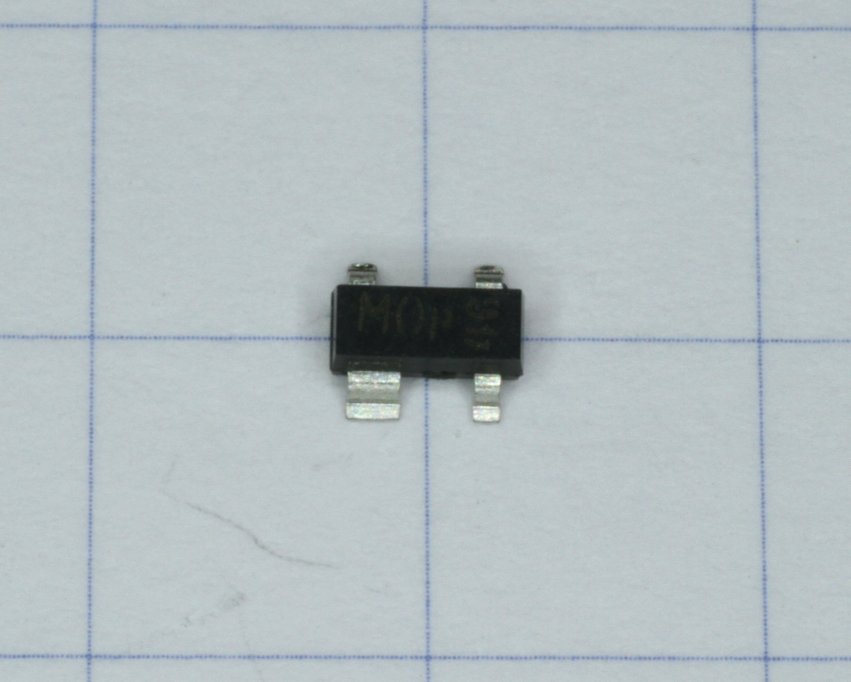 |
460...500 | 0.2 | 150 | BF998 | ||
| SOT-223 | 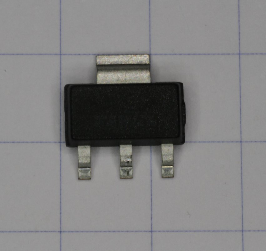 |
120 | 2...3 | 150 | FZT753 | ||
| D-Pack TO-252AA |
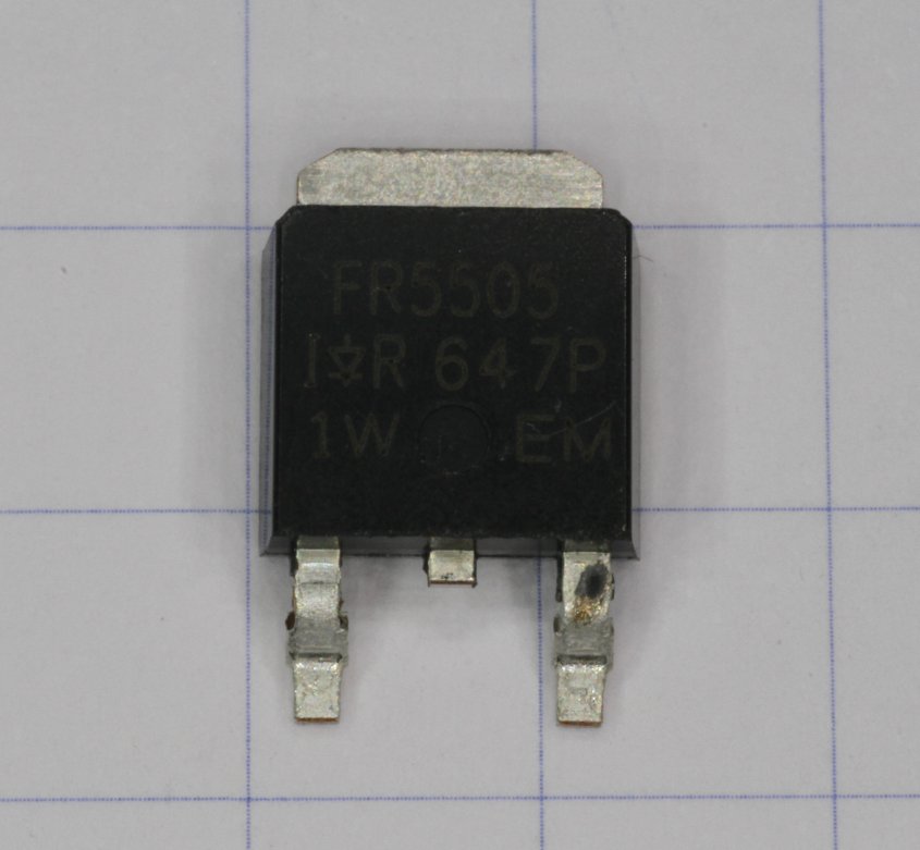 |
1.4...6 | 80...110 | 45...110 | 150...175 | IRFR5505 | |
| SO-8 | 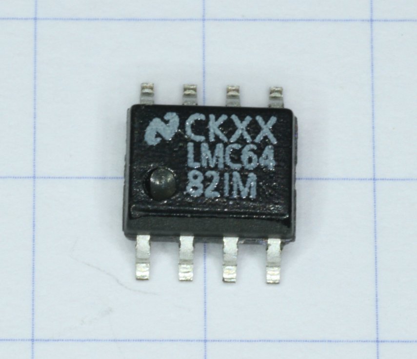 |
25...41 | 100...195 | 0.2...0.73 | 150 | LMC6482 |
Five characteristics can be found in the above table: Rth,J-C, Rth,J-A, Ptot @ TA, Ptot @ TC and TJ.
Rth,J-C is the thermal resistance between the semiconductor junction (say the silicon chip) and the case (or the part of the case that is supposed to be mounted on a heat sink).
Rth,J-A is the thermal resistance between the junction (chip) and the ambient directly. This is particularly important if the component is mounted without a heat sink. When a heat-sink is used, it can be neglected since Rth,J-C is much lower.
Ptot @ TC is the maximum thermal power that the transistor can resist while accepting a high case temperature, while Ptot @ TA is the power while keeping the transistor case at ambient temperature (with a very large heat sink). The second value is usually much larger. Keep in mind that with many transistors you have to reduce the power if it's working at high temperature to avoid other problems in the silicon like second breakdown, but this is beyond the purpose of this page. Have a look at the transistor datasheet, if possible.
TJ is the maximum junction (chip) temperature. Usually silicon can go up to 200°C but many manufacturers specify a more conservative 150°C or even less. If you still design using old germanium transistors, Tj should not exceed 90°C. I usually reduce the value specified in the table by 30% to have some safety margin.
The thermal resistance between the transistor case and the heat sink depends on how the transistor is mounted and on the size of the contact area. Small transistors like TO-126 have higher thermal resistance than large ones like TO-3. Again, if you have precise manufacturer data, use it. If not, the following table could give you an idea about this additional thermal resistance.
| Case | TO-126 TO-225AA SOT-32 |
TO-220 | TO-3P | TO-3 | |
| Picture | |
|
|
|
|
| Mounting method | Example picture | Rth,C-HS [°C/W] | |||
| Direct on heat-sink, no grease |
 |
1.4 | 0.8 | 0.4 | 0.25 |
| Direct on heat-sink, with thermal grease |
 |
0.9 | 0.5 | 0.25 | 0.15 |
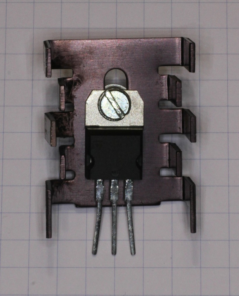
| Insulated with mica, no grease |
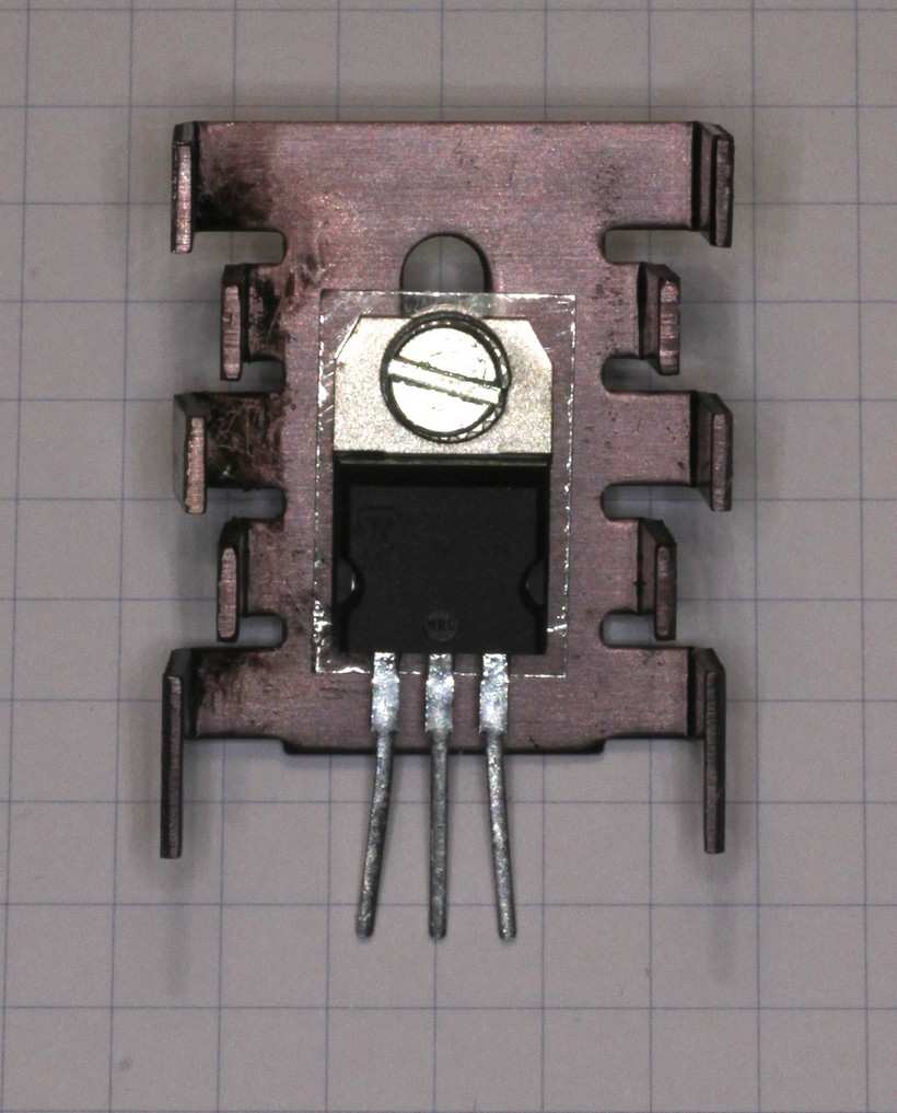 |
2.3 | 1.5 | 0.8 | 0.6 |
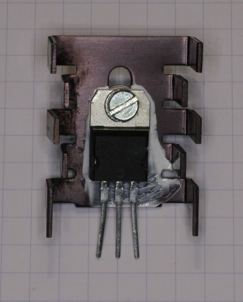
| Insulated with mica, with thermal grease |
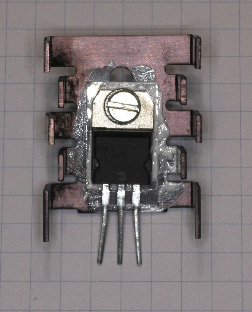 |
2.0 | 1.2 | 0.6 | 0.4 |
| Silicon insulator, no grease |
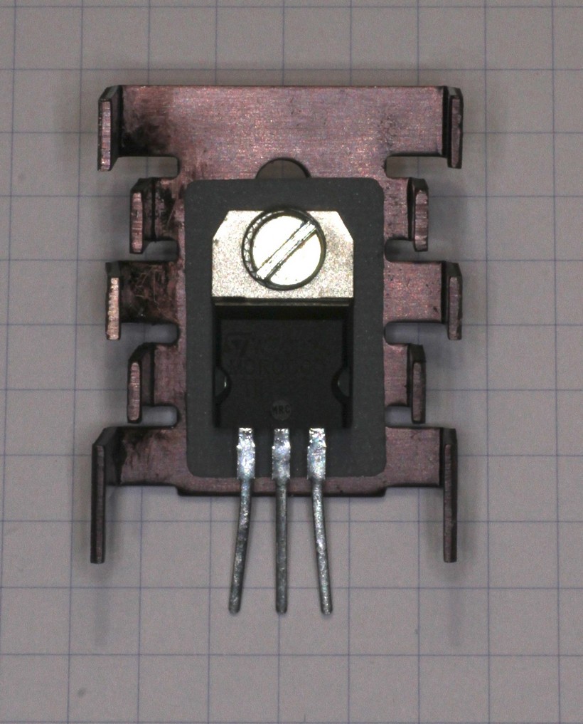 |
2.1 | 1.3 | 0.7 | 0.4 |
There are several way to mount a transistor on a heat sink depending on the need to have electrical insulation between the transistor and the sink or not. There is a delicate balance to find between thermal efficiency, safety, assembly time and electrical performance. If no electrical insulation is needed, this results in a better thermal contact, but this solution is not always possible. Often the heat sink needs to be grounded, especially if, for safety reasons, it's located on the outside of the enclosure. Internal heat sinks can be insulated from the chassis and floated at a different potential allowing direct mounting of the transistors, but stray capacitance may still be an issue at high frequencies. Internal heat sinks are less efficient than external ones, unless a blower is used.
If the transistor needs to be insulated, a thin thermally-conductive electrical insulator foil must be used. There are basically two types of these insulators: micas and silicon based insulators. Mica foils are thin, hard, brittle and transparent. They look very similar to glass and break easily when bended. Silicon based insulators are a bit thicker, flexible, rubber like foils.
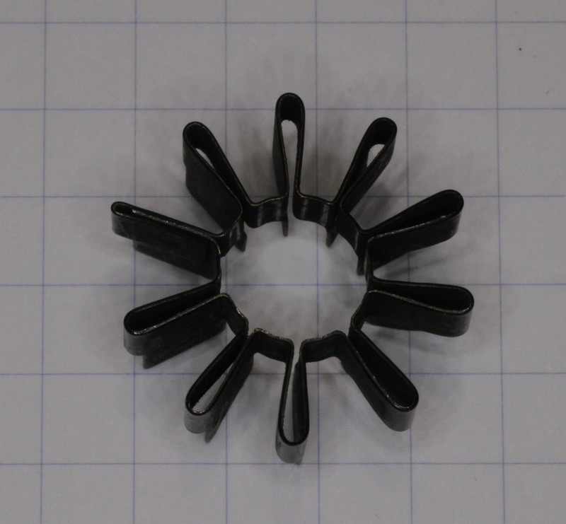
If your transistors are accessible from the outside (like TO-3 on external heat-sinks), you should put insulating covers on them to prevent accidental contacts and potential short circuits caused by external metal objects.
Don't even think about using a piece of cardboard or plastic to insulate your transistors: the vast majority of electrical insulators are bad heat conductors resulting in poor heat transfer. Your transistor won't last very long! Use only mica or special designed insulating pads.
The problem with mica (and all hard surfaces) is that the surface is not perfectly smooth preventing a perfect heat transfer. Specially designed heat-sink grease is generally used; it's thermally conductive but an electrical insulator. This grease fills the microscopic gaps between the two surfaces and improves heat conductivity. It's an excellent idea: always use it with mica pads (on both sides) and even when transistors are mounted directly without any electrical insulation: the thermal conduction is significantly improved. Only very little grease is required: just put a mm3 or so in the middle and it will mostly squeeze out when you tighten the mounting screw(s).
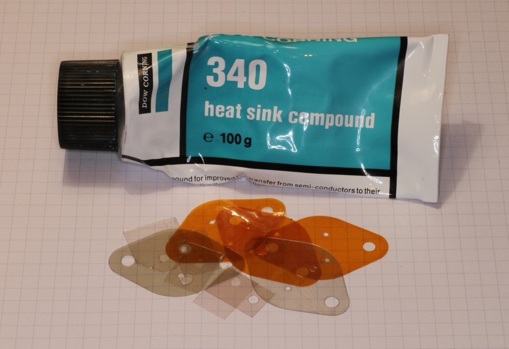
This picture shows a mica insulating pad and a tube of thermal grease.
But there is an alternative to mica and grease: silicon based pads. They are soft: when squeezed they fill the gaps and make a good thermal contact. No grease is required, so you wont have your hands (and cloths) full of that white stuff.
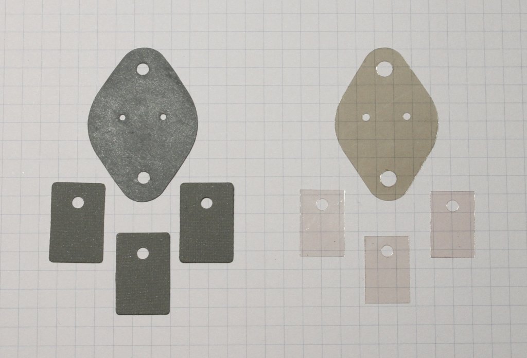
This picture shows some silicon based insulators on the left and some mica
insulators on the right.
When mounting power transistors on heat sinks, don't use plastic screws: they soften with heat and they don't push the two surfaces together anymore, resulting in a dramatic increase in thermal resistance. Use metal screws with insulating bushings and a spring washer. The bushing prevents the screws from touching the transistor and the spring washer keeps pushing all the parts together even when the metals contracts and expands following thermal variations.
In the following picture all the necessary elements for correctly mounting a transistor are shown: from left to right we have first an M3 screw of suitable length. If using imperial screws, #4-40 are generally used. Than there is an optional wire tag if you need to connect a wire to the transistor body. It follows an insulated bushing and the power transistor. Than we have the silicon based insulation pad (that can be replaced with a mica foil wetted on both side with thermal grease) and the heat sink. If the heat sink doesn't have a threaded hole (like this one), on the other side you still need a washer and a nut.
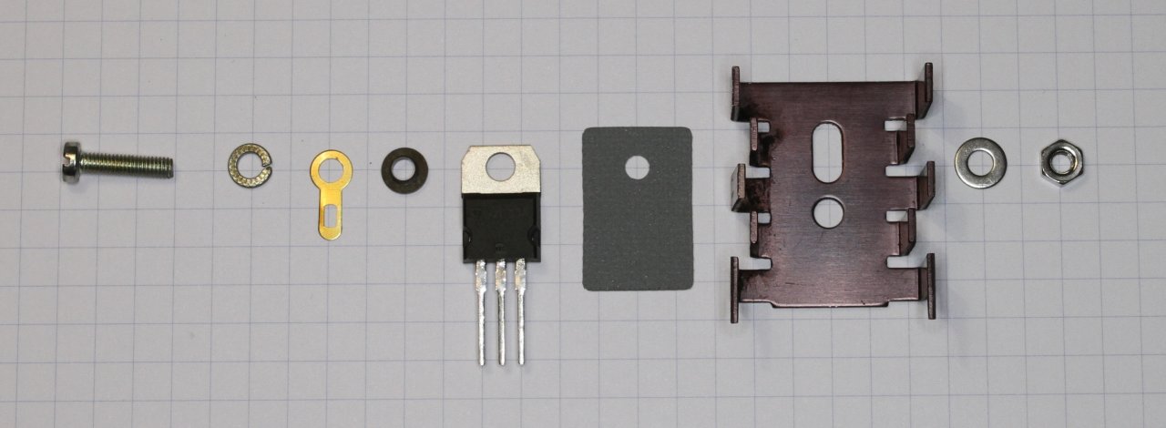
This picture shows all the necessary component in the right order to
mount a power transistor on a heat sink.
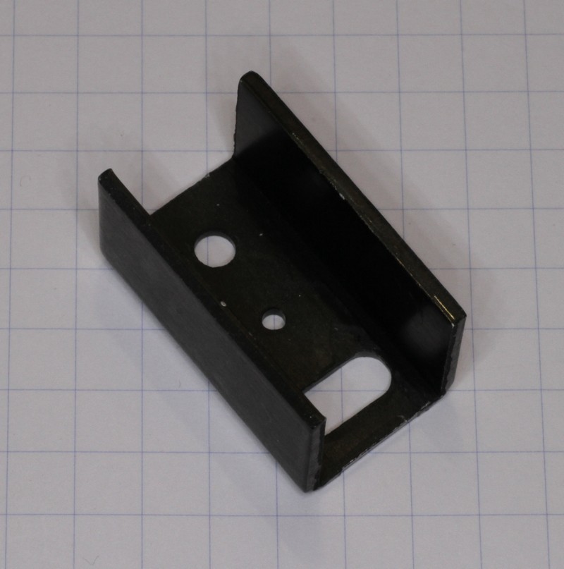
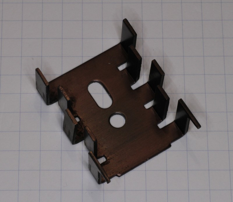
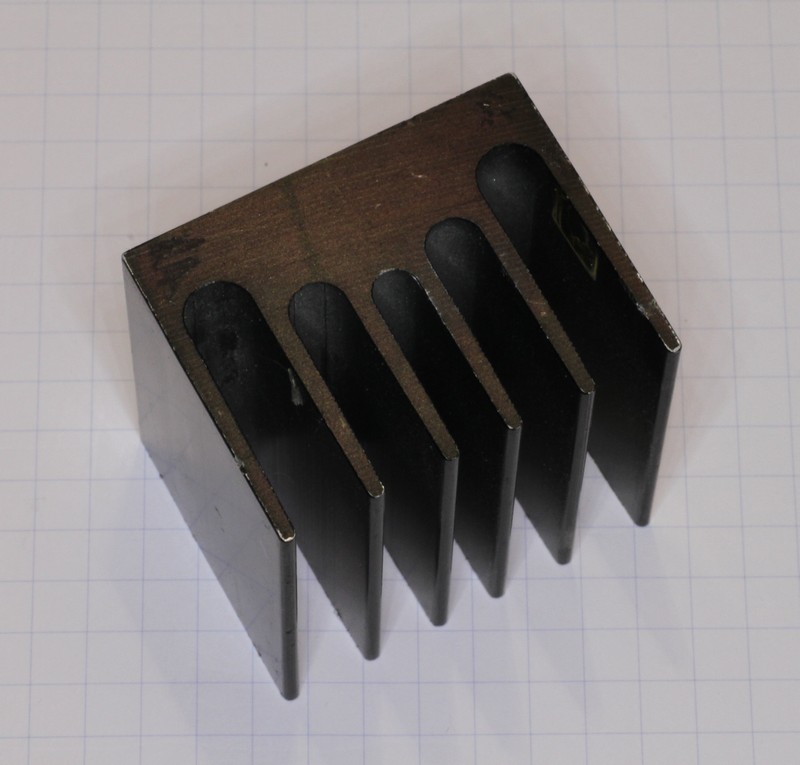
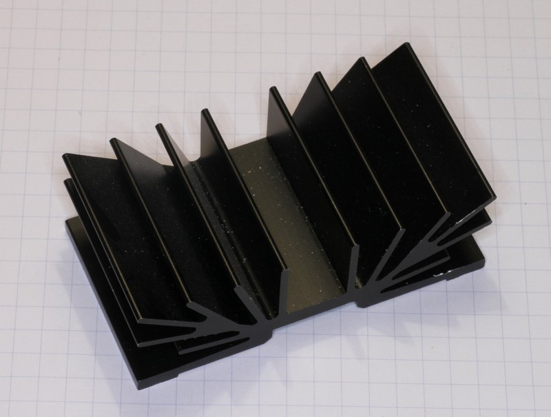
When you buy a new heat sink, you usually have all the necessary information in the datasheet provided by the manufacturer. But when you use a second hand heat sink out of your junk box, chances are that you won't find any precise data. So, the following table will be helpful in finding a similar heat sink and guess the thermal resistance. Large heat sinks have low thermal resistance and vice versa.
| Heat sink picture | Dimensions | Rth,HS-A [°C/W] |
 |
Ø19 mm × 10 mm | 50 |
 |
15 × 11 × 16 mm3 | 38 |
 |
15 × 25 × 15 mm3 | 30 |
 |
16 × 25 × 16 mm3 raw alluminium | 20 |
 |
16 × 25 × 16 mm3 black anodized | 17 |
 |
25 × 27 × 13 mm3 | 15 |
 |
16 × 38 × 16 mm3 | 13 |
 |
38 × 40 × 30 mm3 | 7 |
 |
70 × 38 × 25 mm3 | 4 |
 |
180 × 130 × 48 mm3 | 0.8 * |
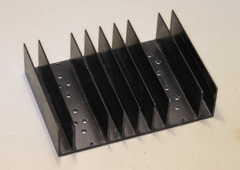
*: Since this heat sink is intended for 4 transistors, each one sees a thermal resistance 4 times higher. When mounting more than one transistor on the same sink, imagine cutting it in equal parts and than place each transistor in the middle of each "section"; don't put them close together on one side of the sink.
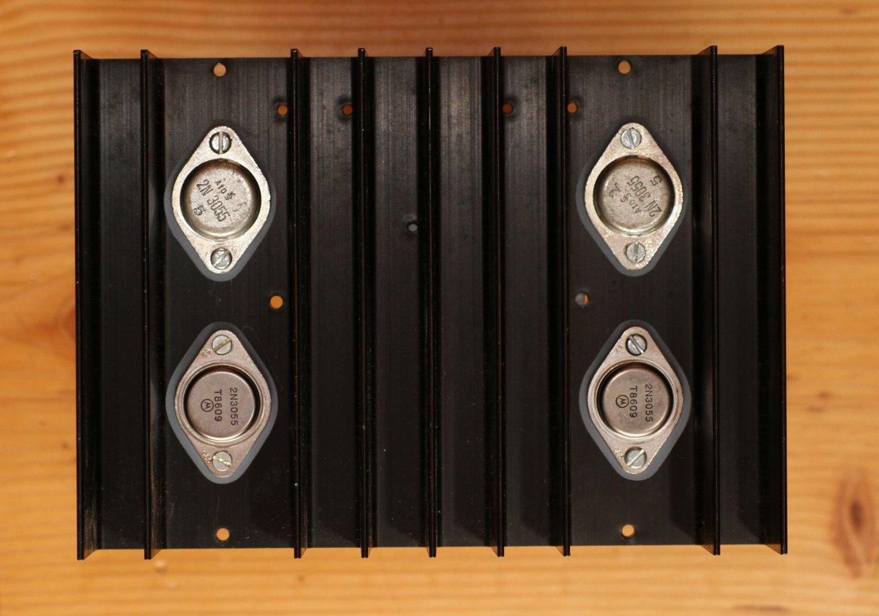
Correct mounting positions of four power transistors on the same heat
sink.
The red dashed lines represent the virtual division in four equal smaller
heat sinks.
Please keep in mind that clear metal heat sinks have 10% higher thermal resistance than black anodized ones, and this is the reason why the large majority of heat sinks are black: they are just more efficient.
If you mount your heat sink horizontally instead if vertically, the natural airflow will be less effective and the thermal resistance will increase by about 25%.
Small heat sinks composed by just a piece of sheet metal (aluminium) can be calculated with the following empirical formula [1], which is only valid for small surfaces, say less than 100 cm2:
Where AHS is the surface of the metal plate in cm2 and Rth,HS-A is the thermal resistance from the heat sink to the ambient in °C/W.
The metal surface is supposed to be untreated (shiny metal colour) and the thickness should exceed 1.5 mm. The heat sink is supposed to be mounted vertically, vertical bends are not relevant. Of course, the metal plate should be as square as possible (or slightly rectangular) and the hot transistor should be placed in the middle. If the shape of the metal is a very long rectangle, the resulting thermal resistance will be higher. Decrease the thermal resistance by 10% if you use black anodized aluminium. Use exclusively good heat conductors such as aluminium or copper.
The following calculator will compute this formula for you:
When a blower is used to force the air through the heat sink, the situation gets more complicated. The following empirical formula greatly simplifies the problem [1]:

Where F is a dimensionless factor and D is the airflow in m3/h.
So, the actual heat sink thermal resistance is reduced by the (multiplicative) factor F based on the airflow: the greater the flow the smaller the factor F.
This formula is only valid with flows ranging from 30 to 350 m3/h.
The following calculator will compute this formula for you:
When using a blower, one should make sure the complete airflow passes through the whole heat sink, just blowing on the sink form a distance is not enough. Please also keep in mind that you need to create a "channel" to force the air through the heat sink. The flow has to be arranged in such a way that the air can enter the blower from one side, go through the sink and exit from another side. Just blowing the same air inside a sealed enclosure has very little effect: you have to allow fresh air to enter the enclosure and hot air to exit from another side. Try to avoid placing the air inlet and outlet on the same side of the enclosure to avoid sucking back hot air. The size, the shape and the amount of holes that let the air in (and out) is important and can dramatically reduce the blower airflow: the more open surface, the better.
Sometimes blowers do fail and your circuit may overheat: it's a good practice to include a thermal switch on the sink that will shut off the power if the temperature rises too high.
You may think that the ambient temperature Ta is the easiest number to figure out, but it deserves a wise evaluation. Some people choose 20 °C for the room temperature, some others choose 25 °C or even 27 °C (300 K), but these temperatures are too low for our calculation. One should always consider the maximum possible working temperature of the circuit: in hot summer day you may easily exceed the above values. For home applications, values around 50 °C are usual, for industrial applications is not uncommon to go up to 60 °C or more.
Than, if you don't have a blower and all the cooling is done by natural convection, it's safer to further increase it by 5 to 10 °C, especially if you heat sink is internal. The reason is because without a blower the temperature in the neighbourhood of the heat sink is higher than in the rest of the room.
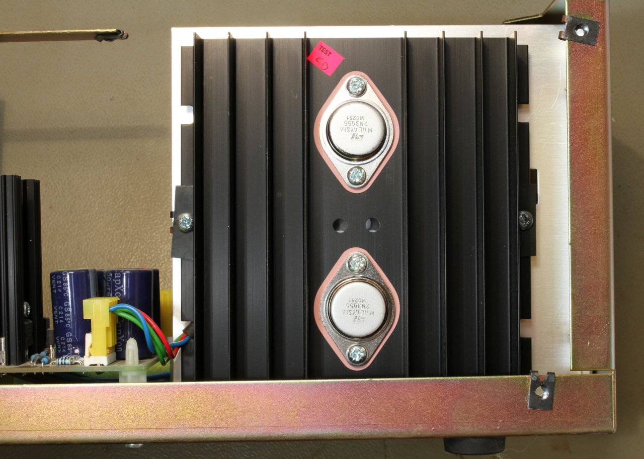
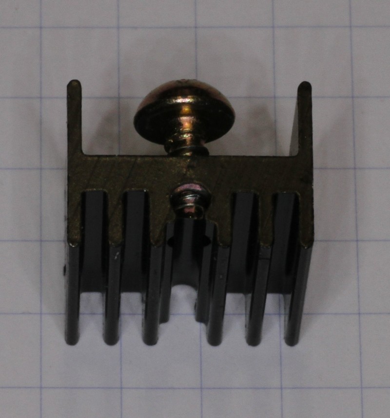
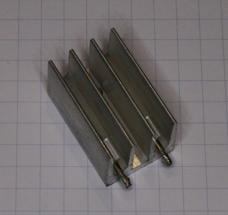
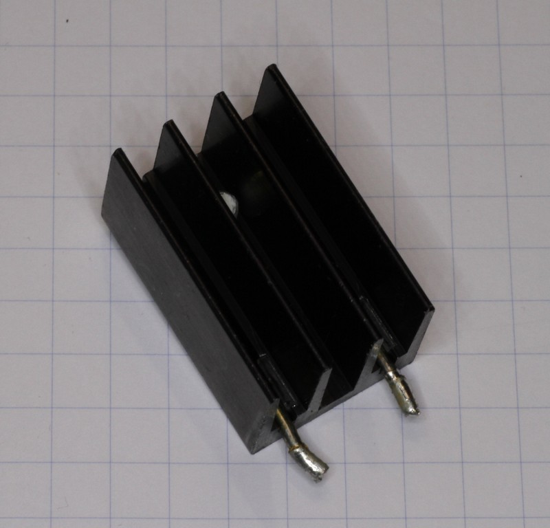
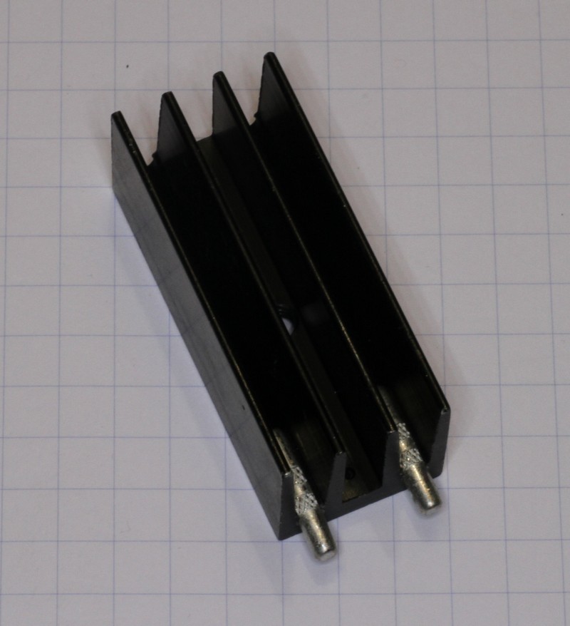
Picture of an internal heat sink.
Please remark how the two transistors are disposed on the sink so that
each one is in the middle of its own half heat sink.
When using an internal heat sink, make sure you have large venting grids on the bottom and on the top of the enclosure to allow sufficient airflow through the sink. Natural air convection always flows upwards: the air inlet and outlet should be very close to the heat sink avoiding inefficient long horizontal paths.
A simple method to design the heat sink and the thermal flow of power semiconductors has been presented. A lot of usual values for common components are summarized in several tables to do some "good guessing" if precise data from the manufacturer is not available, as it's almost always the case when you build something with the components of your junk box.
All thermal designs need to be verified in practice, especially if you did a lot of guessing. Letting your circuit work for several hours while monitoring the temperature will let you know how good your calculation is and if you're coming to close to the maximum temperature, you'll probably need to modify a bit your design.
| [1] | Nuova Elettronica. Accidenti come scotta questo transistor. 1978, volume 11, pages 58-102 |
| [2] | Nuova Elettronica. Tutto sulle alette di raffreddamento. 1995, rivista 180, pages 2-21 |
| [3] | P. Horowitz, W. Hill. The Art Of Electronics. 2nd Edition, Cambridge University Press, 2001, pages 312-316 |
| Home | Electronics | Page hits: 159653 | Created: 11.2013 | Last update: 11.2013 |