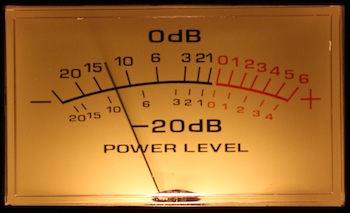
A VU-meter is a very common instrument usually installed on audio Hi-Fi amplifiers and is used to show the instantaneous power provided to the speakers. It is usually connected at the output of the amplifier, in parallel with the speaker. The term "VU" stands for Volume Unit and should be defined with 0 VU being equal to +4 dBm, or 1.23 RMS across a 600 Ω load. 0 VU is often referred to as "0 dB" and volume units are very rarely used. In consumer electronics amplifiers this standard is rarely met and the meters only somehow display the power of the amplifier without referring to any physical unit. Anyway, the only thing one probably wants to know is how much power the amplifier is providing to the speakers and nobody really cares about volume units. So a meter that gives a reading between zero and the maximum power output is fine enough (at least, for me).
The audio volume is often expressed using a logarithmic scale because the feeling of sound intensity we get from our ears is also logarithmic and a direct power reading in Watts would not be very representative of the perceived volume. For example, a few millivolts on an 8 Ω speaker are clearly audible. When listening at low volume, the voltage on the speakers is only a few hundreds millivolts (these are only milliwatts). When the volume is raised to a medium setting, the voltage on the speaker is around few volts (the power is around a Watt) and only when the volume is very high that all the watts of the amplifier are required.
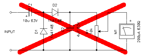
Non-professional audio amplifiers often have simple (and useless) VU-meters. For example, the circuit diagram shown in the figure below was found in my stereo set (rated 80 WRMS on 8 Ω) and is composed by a diode rectifier (actually a voltage doubler composed by C1, D1 and D2), a filter capacitor (C2) and a microammeter (M1). The full scale is adjusted via R1 to match the maximum power output of the amplifier. But with this simple circuit, the reading is proportional to the peak output voltage which is always very low and goes up only when the volume is really too high. So the amplifier has two nice meters that almost never move. Furthermore, the use of a voltage doubler is very surprising (and a bad idea), first because the voltage on the speakers is already high enough and there is no need to double, than because it's composed by silicon diodes that have a forward voltage drop of about 0.6 V while germanium or Schottky diodes would drop much less, and finally because a doubler has twice the forward voltage drop of a single diode preventing small signals to go through. In this configuration, any signal lower than 1.2 Vpeak has no chance of moving the meter. So this diagram has a big red cross: it's a bad idea, don't use it.
In order to have meaningful readings, the meter should be logarithmic, allowing measures of low and high power levels without the problems mentioned above. Professional or high-end amplifiers have good meters with logarithmic converters built with many op-amps and lots of parts, but there is a way to build a simple and passive logarithmic VU-meter with only a few parts. And useless linear meters like the one just described can easily be converted too.
The basic idea is to use the logarithmic characteristic of diodes to obtain a logarithmic response of an electromechanical microammeter. The circuit is shown below and is really very simple. It's based on a standard 200 μA microammeter which is very very common for this kind of applications. Its internal resistance is not critical at all and is usually between 500 Ω and 1 kΩ. The circuit is intended to fit an amplifier capable of 80 WRMS driving a 8 Ω load, but can easily be adapted to other power levels or impedances. Similar power levels requires no modification, for much higher or lower levels, R4 must be modified and maybe also R2 and R3.
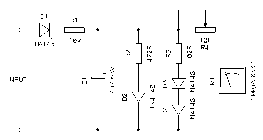
First the AC signal across the speaker is rectified by diode D1. D1 should be a germanium diode or a Shottky diode to minimize the voltage drop across it. Every millivolt lost here will reduce the sensitivity at low volume. But D1 has to stand twice the peak voltage of the speaker, so the reverse voltage of the diode has to be selected accordingly. For example, 80 W over 8 Ω have a voltage of √ 80 W · 8 Ω = 25.3 VRMS and a peak voltage of √ 2 · 25.3 V = 35.8 Vpeak, so the diode will get 2 · 35.8 V = 71.6 V on its leads. Germanium diodes have a low voltage drop, about 0.25-0.3 V, but the majority of them have breakdown voltages between 30 and 40 V! Small signal Schottky diodes can have voltage drops in the 0.2-0.4 V range depending on the model and can easily deal with reverse voltages up to 100 V. Don't use high current Schottky diodes or silicon diodes because their voltage drop is in the 0.5-0.7 V range and is too high for this application.
Resistor R1 is a very good idea because it increases the impedance of the meter and limits the (non-linear) current drawn by this circuits so that it can be neglected compared to the main speaker current. Otherwise, connecting a rectifier in parallel with a speaker could introduce some distortion. The 10 kΩ of R1 are high enough compared to the 8 Ω of the speaker to make sure that the total harmonic distortion won't be affected. R1 will also limit the current in D1 if the maximum diode reverse voltage is exceeded, preventing damages in case of small peaks. Capacitor C1 integrates the rectified signal and provides only DC to the meter. The time constant is below 50 ms, low enough not to slow down the meter that has usually a time constant in the 300 ms range.
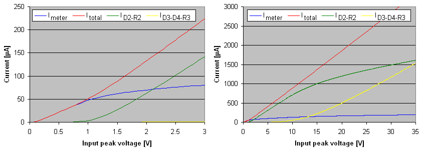
Now the tricky part: for low voltages, D2, D3 and D4 do not conduct. These are regular small signal silicon diodes with a forward drop of 0.6 V; here a high voltage drop is important. So for low voltages D2, D3, D4, R2 and R3 can be neglected and the current can flow directly in the meter. This can be observed in the graph below (the one on the left): for input voltages below 0.6 V, the current in the meter (blue trace) is linear and D2 (green trace) and D3-D4 (yellow trace) conduct no current. As soon as the voltage rises, D2 starts conducting and robs current to the meter making it less sensitive to higher voltages. On the same graph, above 0.6 V the current in D2 (green trace) starts rising and the current in the meter (blue trace) rises with a lower slope. For even higher voltages (about 10 V, graph on the right), D3 and D4 will start conducting as well robbing even more current (yellow trace). The effect is that the meter current slope (blue trace) is further reduced approximating a nice logarithmic function. To calculate this circuit (especially the values of R2 and R3), the common approximation of the 0.6 V threshold voltage is not enough. One has to use the diode characteristic exponential function, but equations get complicated and I wasn't able to solve it with just a pencil and a piece of paper. Fortunately, free SPICE software is available and the circuit can easily be simulated and a reasonable solution can be found by modifying the values of these to resistors until a suitable response is achieved.
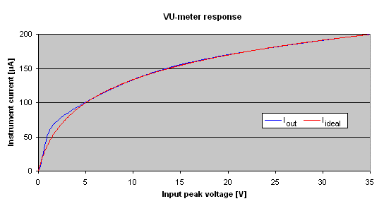
The figure below shows in blue the response of this circuit and compares it to a perfect logarithm in red. As one can see, the performance of such a simple circuit is pretty good. Probably, spending more time with a simulator, one could achieve an even better result, but I decided it was good enough for me.
Trimmer R4 is used to set the full scale of the meter. The easiest way to adjust it is, before connecting this circuit to your stereo set, to turn it for the maximum possible resistance, than temporarily connect a DC source to the input corresponding to the maximum peak voltage (35.8 V in this case) and turn it in the other direction to align the needle with the full scale reading. Because of the logarithmic characteristic of this circuit, the correct adjustment of R4 is not critical at all.
Another way to adjust R4 is to install the circuit at the output of the amplifier as usual, apply a test signal to the input, turn the volume for the maximum power and adjust the trimmer for the full scale. The problem with this second method is that the speaker must be connected while doing the adjustment and it's a very loud operation. Of course, you could replace the speaker with a suitable dummy load, if you have one.
In this way, the meter will read the output power of the amplifier and not real VU units, and I think this is the most useful reading. If you prefer real VU units or dBm units, you can still apply the same procedure and adjust for a given power and aim a given mark on the meter instead of the full scale. If not adjusting for full scale at full power, verify that the needle won't hit the full scale end at full power; otherwise the meter could be damaged.
Please remark that the type of rectifier used in this circuit requires a DC path in the source side. This is usually not a problem: tube amplifiers have transformer output that conducts DC, push-pull amplifier with dual power supply are DC coupled as well. Single supply transistor amplifiers, on the other hand, have a capacitor coupled output and a DC path does not exist in the amplifier. But a DC path always exists in the speaker and as long as the speaker is connected the VU-meter will work fine. Don't worry about this DC current, because of the high value R1, its value is only 0.08 % of the main speaker current and can be neglected.
One of the big advantages of this simple circuit is that it's completely passive and requires no power supply. This means it can be connected directly in parallel with the amplifier output (or the speaker) without warring about the amplifier output configuration. No matter if it's a push-pull, a single-ended, an H-bridge, a transformer output or whatsoever. There is no risk of shorting to ground half of the output transistors or shorting together the left and right channel: just connect it fully floating in parallel of the output.
A simple circuit to build a simple logarithmic VU-meter has been presented. Its simplicity really outperforms common linear VU-meters for about the same cost. Even if its accuracy is lower than what is achieved with professional equipment, it's a good logarithmic approximation and is definitely good enough for a Hi-Fi amplifier of a stereo set. Furthermore, this circuit is completely passive, requires no power supply, has no problems with common grounds and can therefore fit any kind of audio amplifier.
| Home | Electronics | Page hits: 138509 | Created: 01.2013 | Last update: 01.2013 |