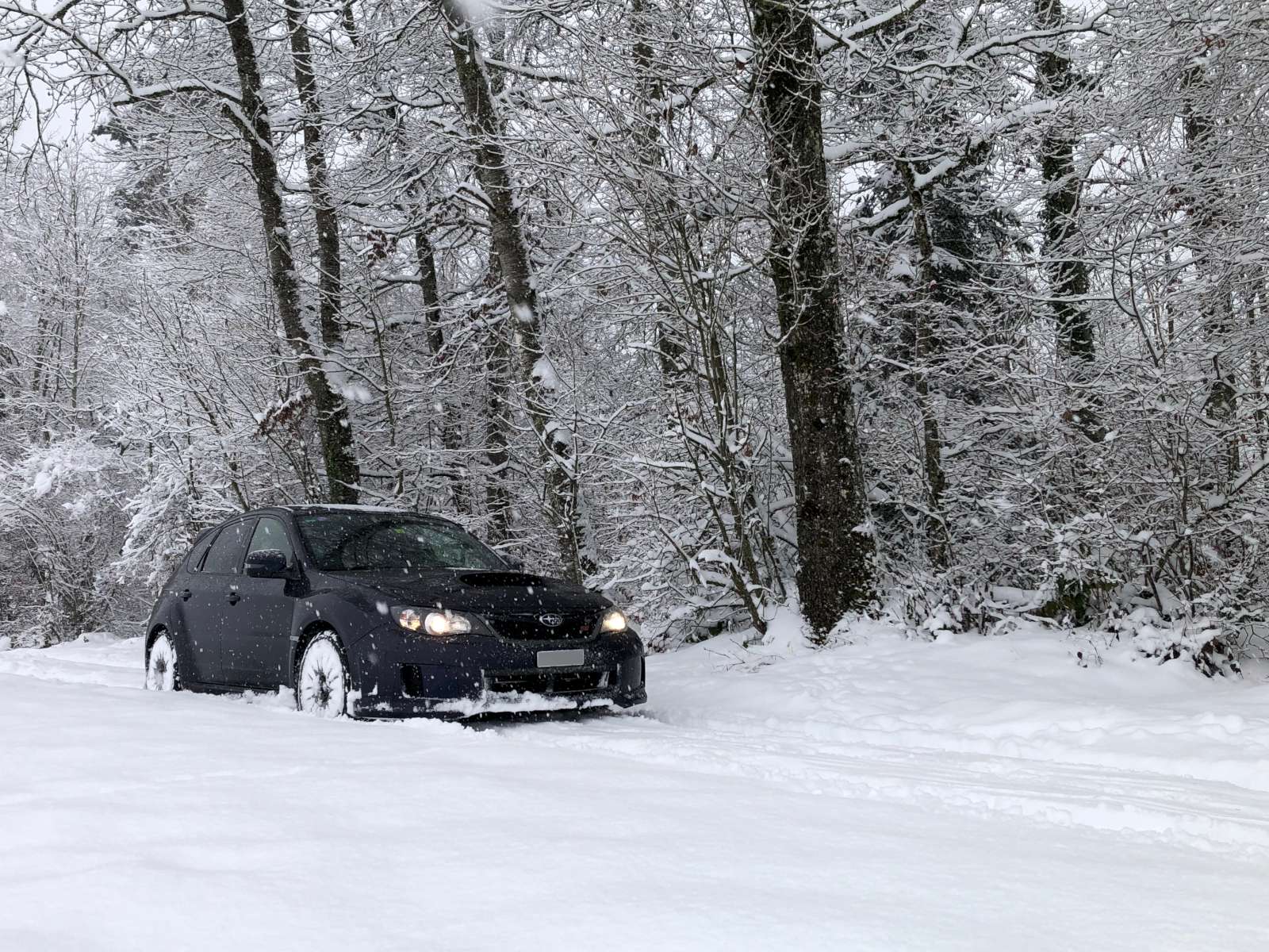
The STi in its natural element: the snow (click to enlarge).
When I was a teenager I was very interested in motorsports and especially in rallying. Maybe because those cars looked exactly like road cars and I believed that I could just walk into any car dealership and buy one. To some extent that was true: there were indeed racing regulations asking manufacturers to produce and sell those cars to the public to be allowed to race, but only a few actually did that. I was particularly fascinated by that blue Subaru with the famous three yellow fives and of course I wanted one. I don't know why that one, the other ones were good too, but that one was the one I fell in love with. And Subaru was kind enough to sell a civilized version of that car called WRX STi. For a teenager like me, that was still beyond reach and I had to get by with a much cheaper small motorbike.
Many years went by and one day I went to the car dealership with my wife to buy a new car for her. And while she was looking at her new "grocery getter" I spotted a brand new STi in their showroom, just a few meters away. The salesman noticed the eager look in my face and told me: "we can make a special offer on that car, do you want to go for a test drive?" Of course I wanted... and I did. He really did the right move: that day we only bought a car for my wife, but shortly after I came back and bought that STi, too.
I really like my STi, and for many reasons. It's not the blue car with the yellow fives of my teenage years, that was only a dream, but it's really a civilized rally car that you can use every day to commute, to do your groceries and to have fun on twisty roads. Brakes are fantastic: you can drive hard as you want and they never fade. The chassis is stiff and sticks to the road like nobody's business. The engine is a bit "old style": the turbo has some lag and needs some revs to spool up, but that "kick in the back"quot; you get when you reach 3'500 rpm is really funny, it makes me smile every time. I prefer it to modern engines that are so linear and lack personality. Then, its permanent all-wheel drive has tons of grip and it's so easy to drive as the throttle will pull you out almost from any corner: you can accelerate a lot earlier than two-wheel drive cars and you quickly become addicted to it.
The STi in its natural element: the snow (click to enlarge).
Moreover, I appreciate that the engineers that designed it had nice thoughts for the final customers and decided to allow them to drive the car "unsafely" and have fun when they want to. Unlike many other cars, the traction control can be fully disabled and you can drift, drive sideways, run donuts, and have fun on the snow if you feel brave enough. If you apply throttle when braking, unlike most common cars, the engine will still deliver the power you ask for and that's a big plus when driving in the snow or in low grip conditions where you want to slow down just a little bit, or when you want to load the front suspension before a corner without lifting and losing the pressure of the turbo.
There is only one thing missing: a turbo gauge. I'm probably not the only one wanting it, as Subaru finally fitted one in the following model in the central display. But my 2012 car lacks it. It's not a necessary instrument; it's just nice to have it. But I like to see how the turbo spools up, how fast the pressure rises and how well it follows the throttle.
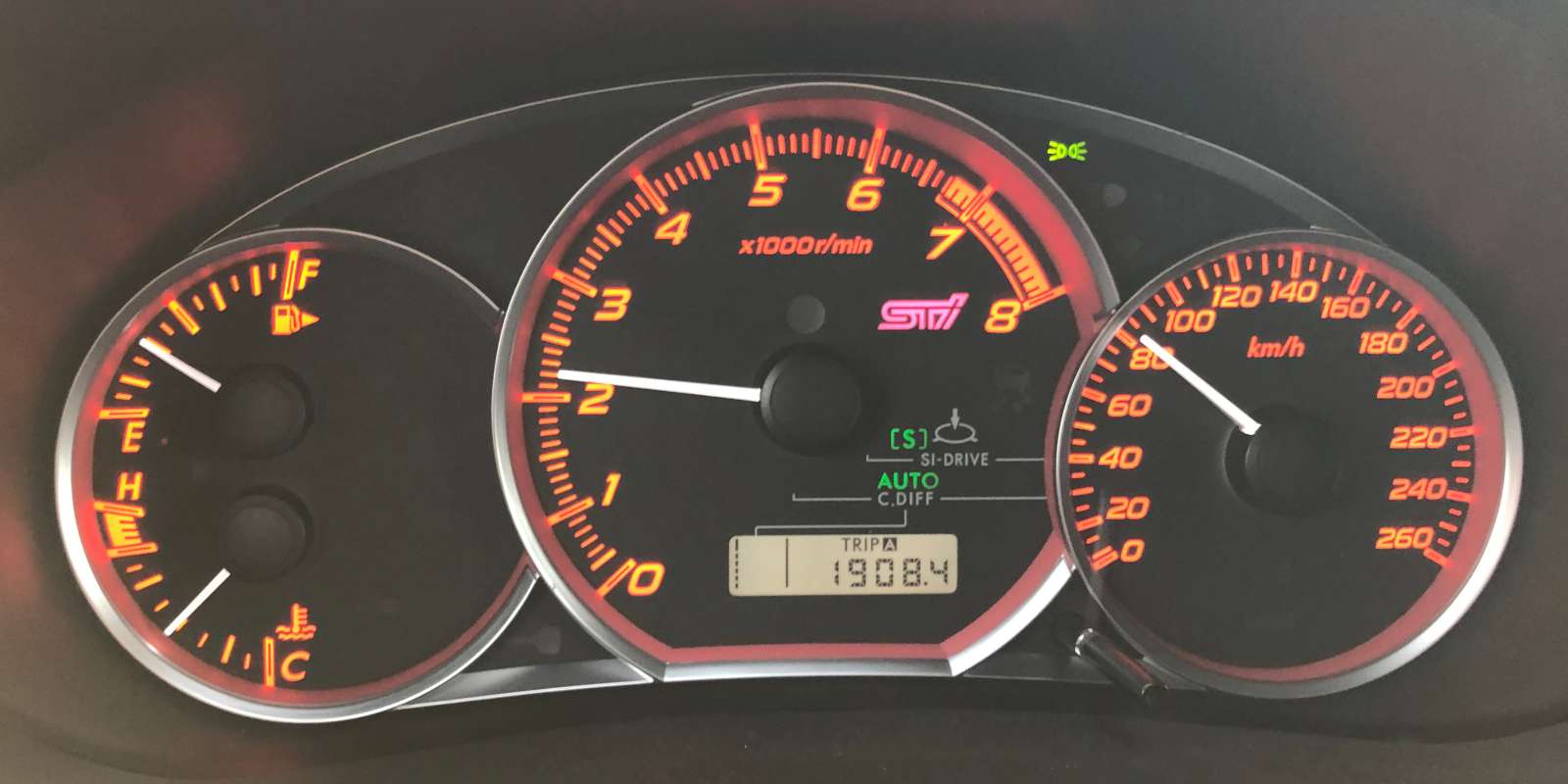
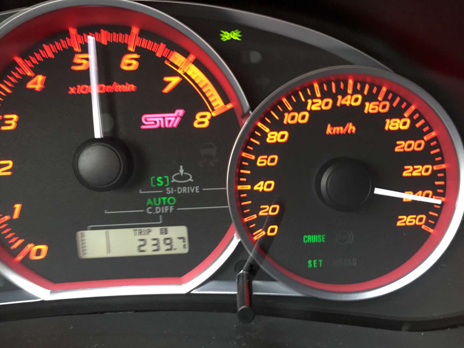
The STi has a beautiful red dashboard but lacks a boost gauge.
(click to enlarge).
Adding a boost gauge is not a big deal: they are quite cheap and not too difficult to install. Just tap off a pipe in the intake manifold, run a pipe through the firewall and install the gauge somewhere near the dash. But I didn't like that approach. Why go through all that mechanical work when the boost information is available in the engine control unit (ECU)? It's much easier to read it through the OBD-II (on board diagnostic) port and display it.
OBD-II gauges exist, but are very expensive and too complicated. I could not find one that was cheap and simple enough to just display boost. Some people built their own gauges, but apparently nobody shared their design with enough details to replicate it. It's a pity. I still find hard to believe that the internet is not flooded with DIY gauge projects, but I couldn't find a single one. This is why I decided to share mine, as I think that many STi owners (with some electronics skills) may want to build their own, too. The second reason I decided to share this otherwise very simple design is because I run into a less obvious electric problem that resulted in a frequent check-engine light and its solution, although very simple as well, may be of some interest, too.
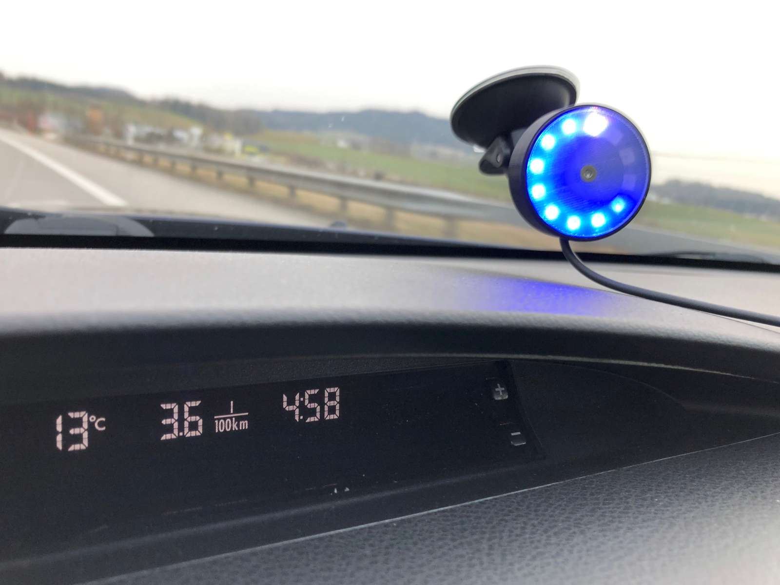
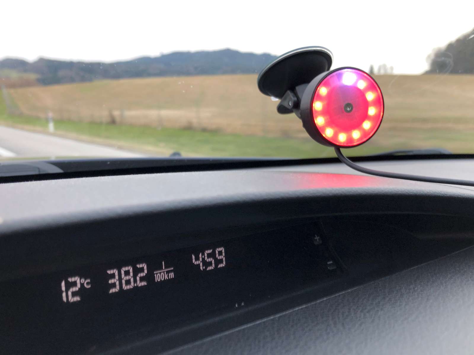
Because I didn't feel like drilling holes in the dash and permanently install the gauge, I came up with the idea of using a suction cup to mount it to the windshield. Because it only has one connection to the OBD-II port under the steering wheel, it's installed or removed in a matter of seconds and requires no tools and no permanent modifications.
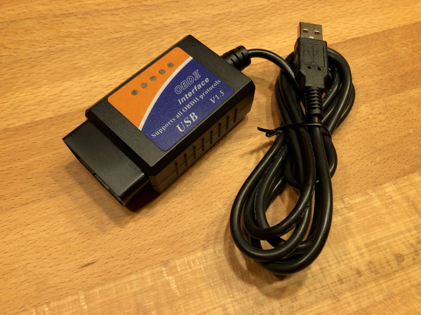
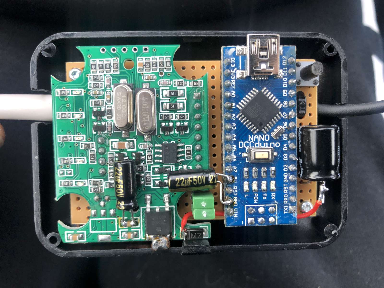
The circuit is really simple and in terms of electronics there is nothing to write home about. Still, I'll describe how it works and how you can replicate it, if you are interested in. You basically need three main parts: an OBD-II to USB converter, an Arduino Nano and a Neopixel ring. All items can be imported for very cheap.
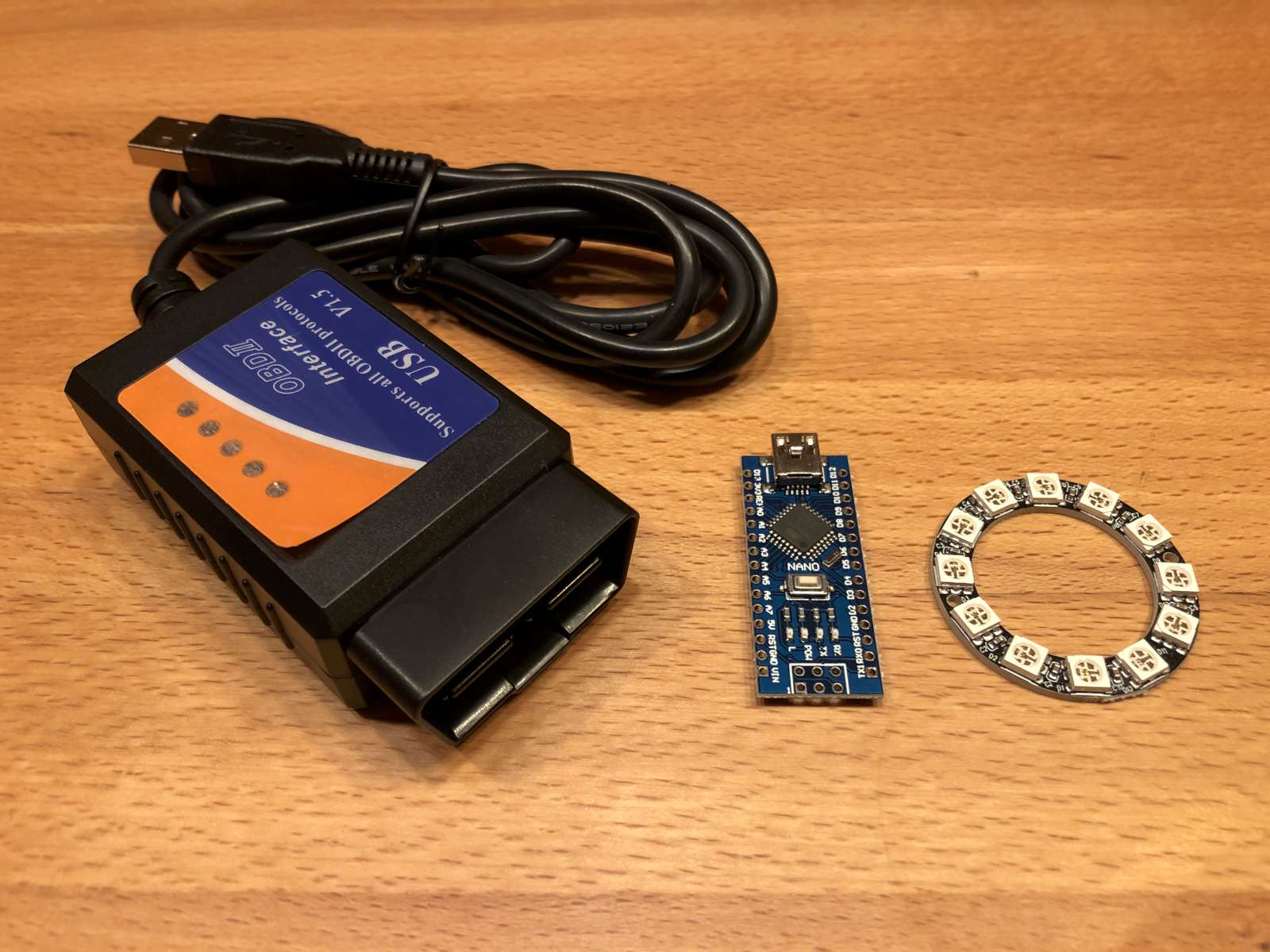
The three main parts of this gauge: the OBD-II to USB converter
(left), an Arduino Nano or compatible microcontroller board (center) and a
12-LED Neopixel ring (right). (click to enlarge).
The circuit described here is accurate with the parts I have, yours may be a little different and be prepared to do the necessary changes as these cheap parts are not all exactly the same. The ring may have different dimensions or pin layout, the OBD-II to USB interface may have a different internal circuit,... so some creativity may be required.
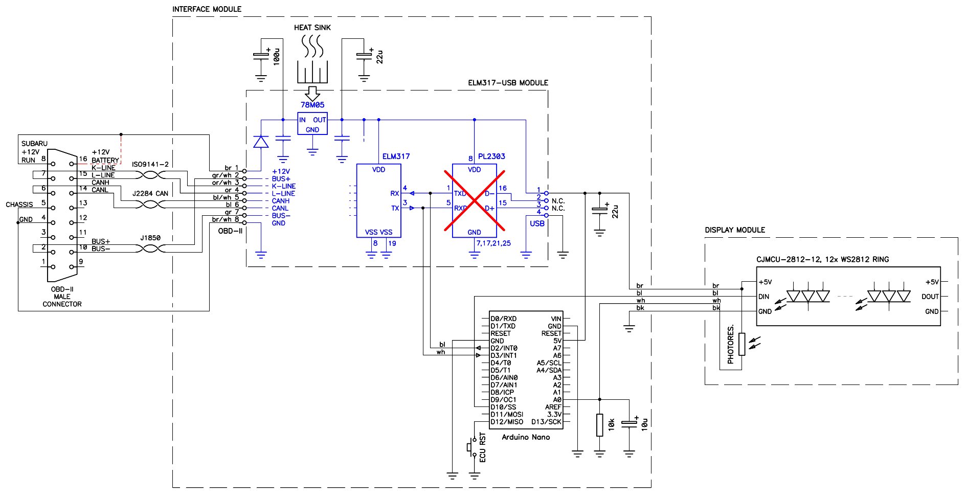
Circuit diagram of the OBD-II boost gauge. (click to enlarge).
Complete PDF schematic diagram: boost-gauge-circuit.pdf (35,306 bytes).
Using an off-the-shelf OBD-II to USB converter saves a lot of work; otherwise one would need to implement all the OBD-II interfaces with a lot of chips and transistors. Furthermore, the converter comes with a built-in OBD-II connector that is hard to source as a standalone part. It's much cheaper to buy it assembled and modify it to your needs, than to buy all the components separately and build exactly the circuit we need.
The original OBD-II to USB converter before being modified.
(click to enlarge).
To work with this project, the OBD-II converter must be based on an ELM327 chip or one of its clones (most of them are, at least in 2021). The ELM327 is an OBD-II to serial interface, and the serial interface is where we want to connect our Arduino. The only thing we don't need from the converter is the USB interface, but removing the corresponding chip is not a big deal. Mine had a PL2303 USB interface. With a sharp cutter, I simply cut all the pins flush to the IC and then cleaned the pads with a regular soldering iron and a copper wick to make sure there are no short circuits left.
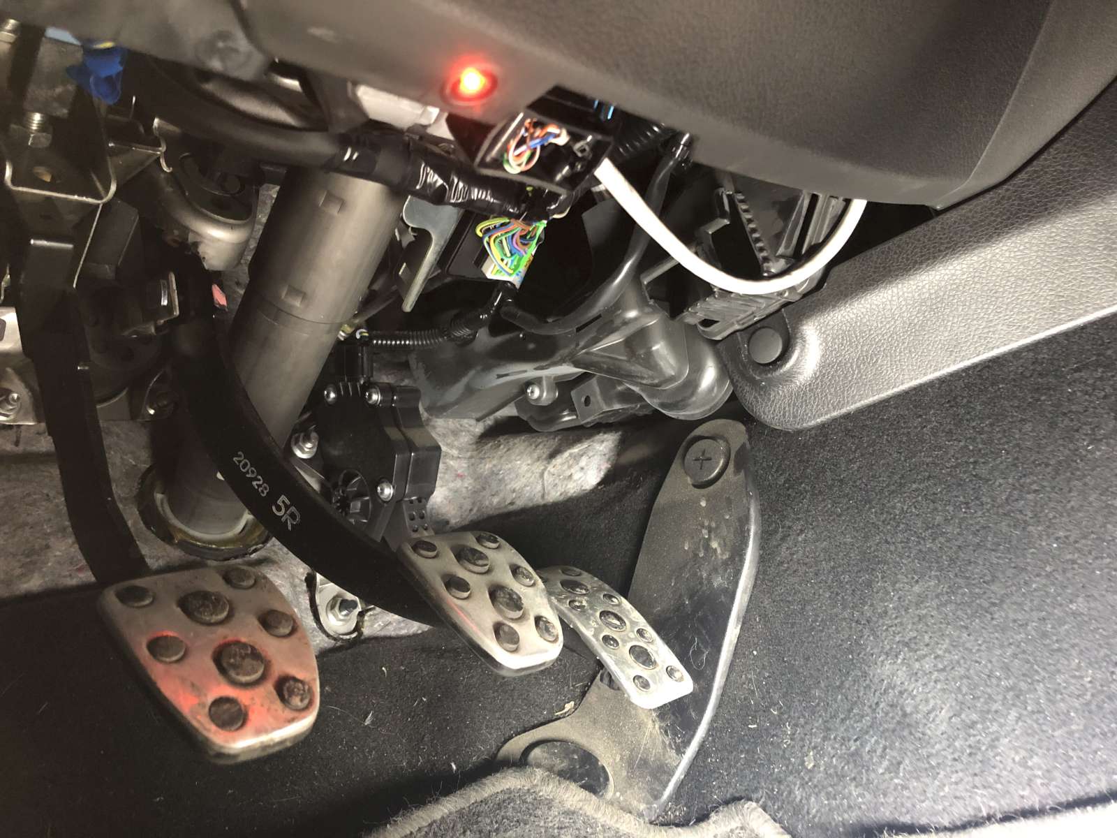
The chopped-off OBD-II plug connected in the vehicle OBD-II socket
under the steering column: it's short enough not to interfere with the legs
while driving. (click to enlarge).
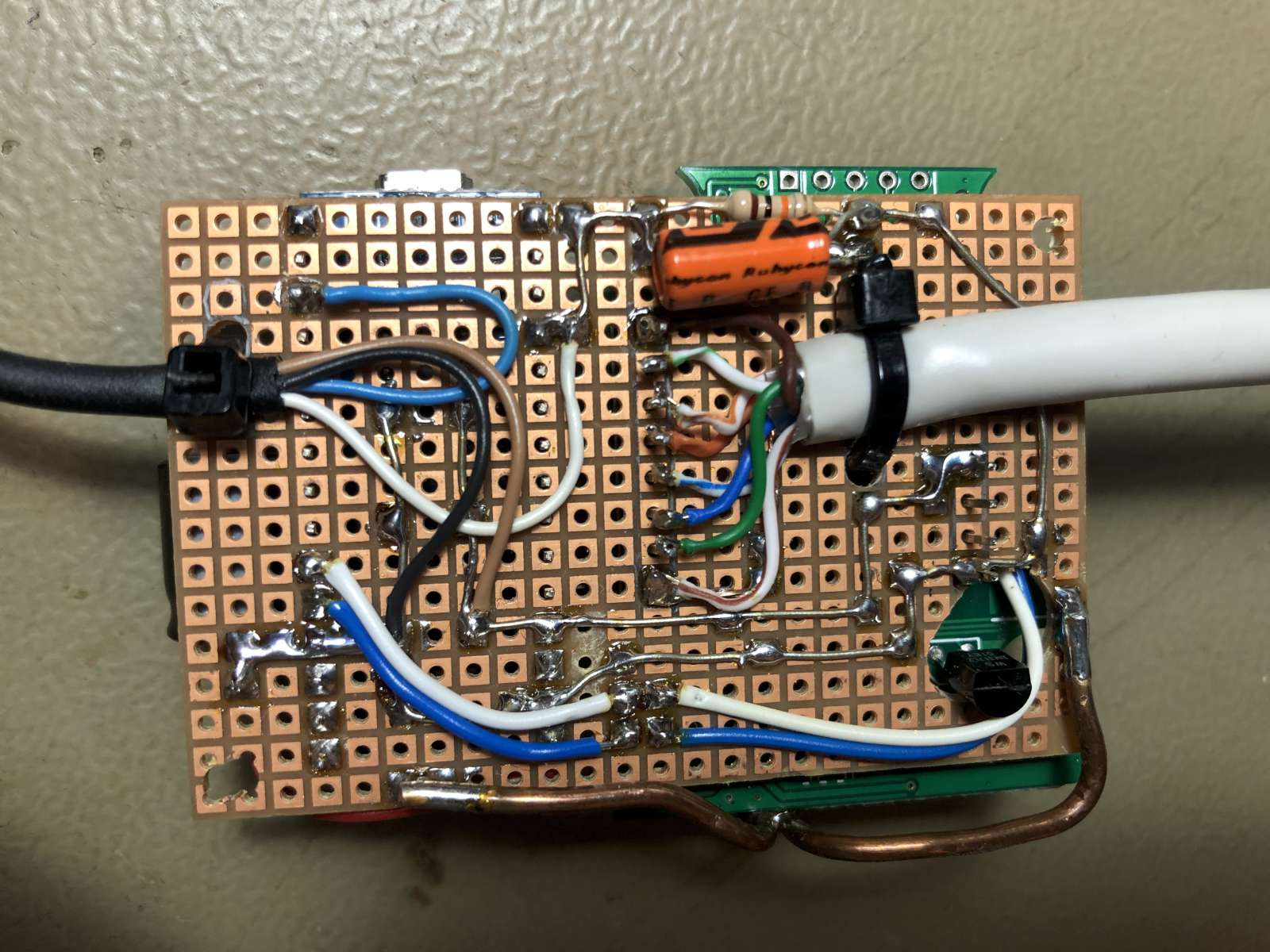
The OBD-II male connector that came with the converter can be reused, but the original case was too long and interfered with my legs while driving. So, I cut the connector casing much shorter, mounted the whole interface in another small plastic box and I used a 30 cm long cable to connect them. Eight wires are needed: three twisted pairs for the J2284 (CAN), J1850 and ISO9141-2 interfaces, and two wires for +12 V and ground. I didn't test it, but probably only the CAN interface is enough. Anyway, since the two other interfaces are available, connecting them doesn't hurt. The CAN bus requires a twisted pair connection with a characteristic impedance of 120 Ω. I didn't have such a cable, so I used a piece of Ethernet CAT5e cable instead. Ethernet cables have an impedance around 100 Ω and contain four twisted pairs: the impedance is not too far off and the number of wires and twisted pairs is almost exactly what we need. The 12 V power wires don't need to be a twisted pair, but it doesn't hurt.
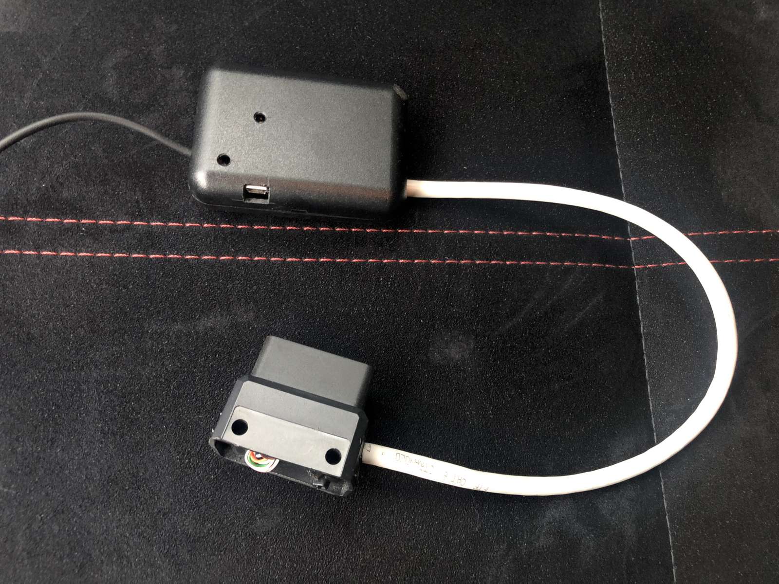
The interface in a small box and (top) and the chopped off connector
(bottom) connected by 30 cm of Ethernet cable. (click to enlarge).
To process the information we use a simple Arduino Nano, which is a tiny board with an ATmega328 microcontroller. I like this solution because it's cheap, because wires can directly be soldered on its comfortable 2.54 mm spaced pads and because it doesn't require any dedicated (and expensive) programming interface: it plugs directly into the USB of your PC.
Four wires connect the Arduino to the OBD-II interface: +5 V and GND to supply power, and RX and TX to communicate with the interface. The initial design used D0 and D1 for communication with the ELM327 because these lines connect to the internal hardware serial interface of the microcontroller. But as these lines are also used to program the Arduino itself, I had to manually open them with two jumpers every time I wanted to reprogram it and I could not use the console to debug it. So I ended up connecting the ELM327 on D2 and D3 and use a software serial interface instead. It works equally well as the microcontroller doesn't have a lot to do to process the data.
For debugging purposes I added a button on pin D12. This button ended up to be quite useful to reset the ECU trouble codes and clear the check-engine light when I had problems during the development of this gauge. It still resets the trouble codes (see below) but there is no need for it anymore now that the circuit works as intended, and it can be omitted.
The display is composed by a ring of 12 Neopixel (WS2812) LEDs connected in a daisy chain. Only one line is needed to drive them and is connected to pin D10 of the Arduino. The LED ring is quite nice and small, smaller than the Arduino or the OBD-II interface. So, to avoid making the gauge too bulky, I decided to separate the LED ring from the rest of the circuit and connect it with a 1 m long 4-wire black telephone cable. Three wires are for the LED ring (+5 V, GND, and DATA) and the fourth one is for a photo-resistor used to measure ambient light. The photo-resistor forms a voltage divider with a 10 kΩ resistor and feeds an analog voltage back on pin A0 of the Arduino. This allows automatically adjusting the brightness of the LEDs to make them brighter in daylight conditions and to dim them down at night.
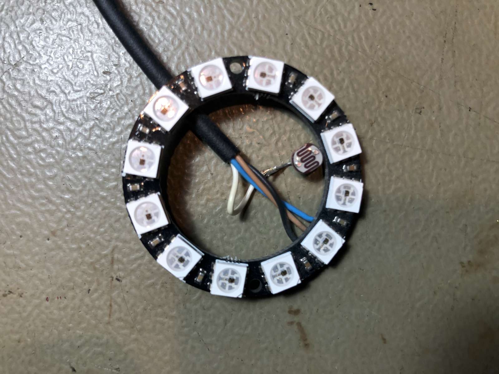
The LED ring temporarily wired during the development phase.
(click to enlarge).
Instead of using a readily available project box, I decided to 3D-print a suitable housing, so that I could keep the dimensions small and have a better looking shape. On the back of the housing I glued a brass insert tapped ¼"–20 which is the standard thread for camera (and suction cups) mount. As an alternative mounting method, I also included the possibility of installing two Ø6 mm, 2 mm thick disc magnets into two recesses.
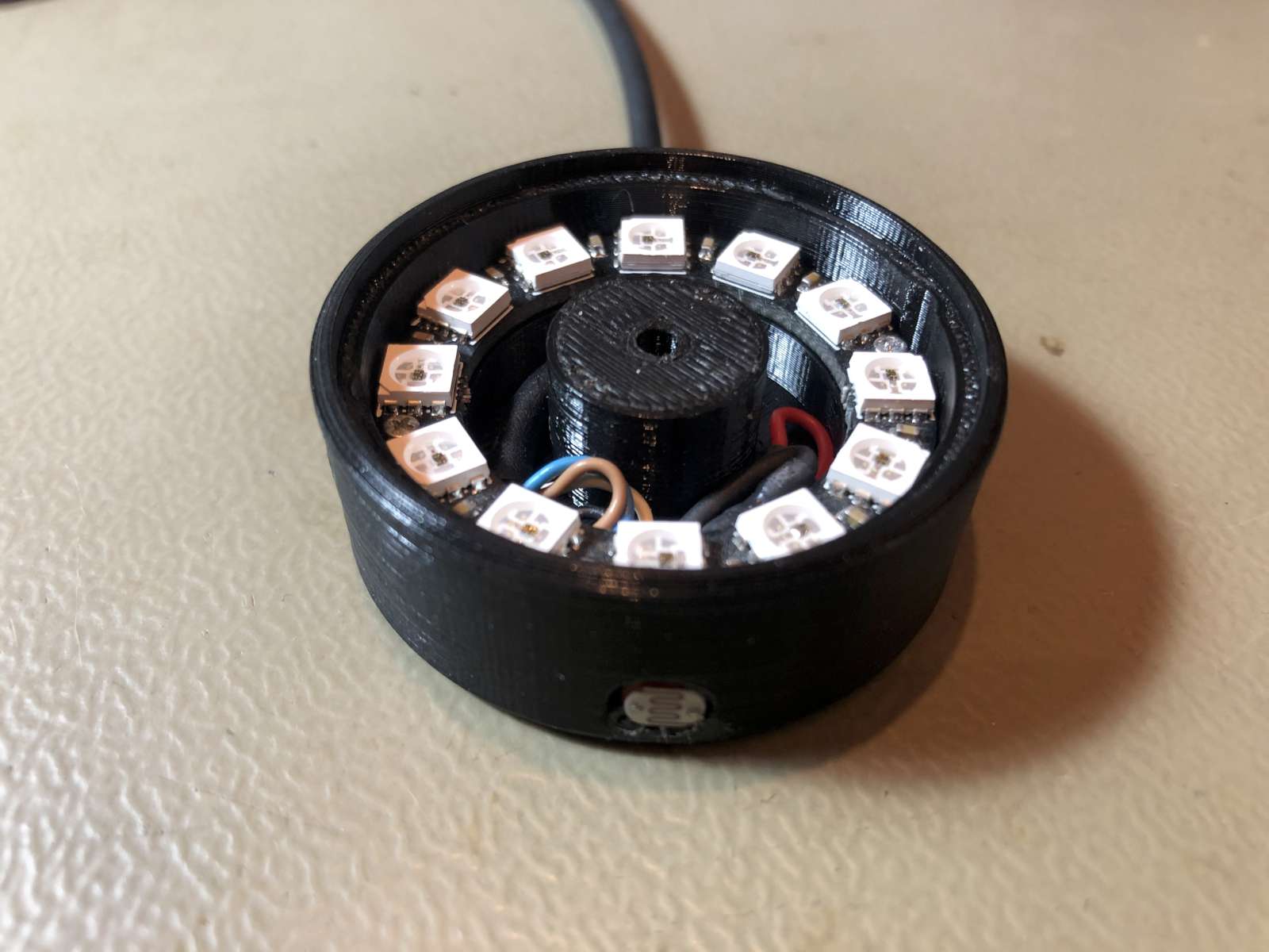
The LED ring in its final 3D-printed housing. (click to enlarge).
For the printing of this housing, I used a black ABS (Acrylonitrile Butadiene Styrene) filament because of it higher melting temperature that is better suited for car applications, as PLA (PolyLactic Acid) may melt if you park the car in the sun in a hot summer day.
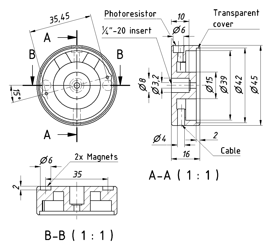
Plan with some dimensions of the 3D-printed housing.
(click to enlarge).
Complete 3D model of the display housing (STL format): boost-gauge-display-case.stl (400,784 bytes).
The transparent glass was initially 3D-printed as well, but I ended up turning a piece of PMMA (Poly Methyl MethAcrylate or acrylic glass) into a disc in my lathe because is more transparent.
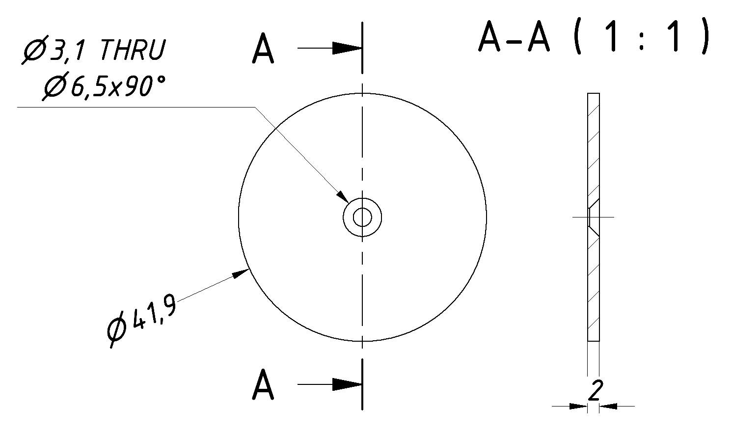
The transparent glass is a simple PMMA disc with a countersunk hole in
the middle.
(click to enlarge).
The brass insert is a simple Ø8 mm rod with two axial tapped holes; a very simple part to make if you have access to a lathe.
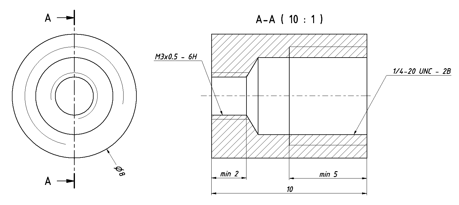
Plan of the brass insert with two axial tapped holes.
(click to enlarge).
An M3×8 flat-head screw in the center of the gauge holds the glass to the brass insert and keeps everything closed. The insert is glued with epoxy; the photo-resistor and the cable are held in place with a tiny drop of hot-glue.
The OBD-II standard defines pins 4 and 5 to be ground and pin 16 to be +12 V. The problem is that pin 16 has constant power all the time, even when the engine is switched off. So the power for our gauge should be taken somewhere else as we want it to turn on or off with the engine. Fortunately, Subaru has been kind enough to provide switched battery power on pin 8. So getting +12 V power from pin 8 works perfectly on Subarus and your gauge turns on or off as intended. But pin 8 is a factory specific pin and has different functions with other brands: if you want to use this gauge on a different car, you should probably get power from a different source (like the cigarette lighter plug) or from pin 16 and install a switch.
By the way, running this gauge when the engine is not running (i.e. when the ignition key is not in the RUN or START position) results in communications errors and the gauge blinks purple. Nothing too bad, though, just start the engine and wait until the communication is back (it takes quite some time) or cycle the power of the gauge and everything is fine again.
The OBD-II converter also has a 78M05 voltage regulator providing 5 V from the 12 V car battery supply. We don't use the 78L05 voltage regulator the Arduino has onboard as it's weaker than the 78M05 on the OBD-II converter, so the VIN pin on the Arduino is not connected and all the power we need is provided by the OBD-II converter's 78M05. Even if this chip has enough capacity for our needs, because of the increased current consumption and its small size (it's a DPAK−3 surface mount package), I decided to add a heat sink. Because I'm a lazy guy, I chose the quick and dirty solution of just soldering a thick solid copper wire to its ground tab. I used about 10 cm of 2.5 mm2 wire that I soldered to the regulator in the middle and run the two ends around the board. The tab is internally connected to ground. Don't be fooled by the crudeness of this heatsink, it works really well: if you don't believe it, just think at how hard it is to solder it while it sinks most of the heat off of the iron. By the way, you need a powerful soldering iron and a wet sponge: as soon as the wire is soldered to the 78M05 cool everything down by rubbing the wet sponge on the wire and on the regulator. This will prevent the chip from staying too hot for too long.
Top view (left) and bottom view (right) of the "ugly"
prototype board used to build this interface.
Please remark the copper wire used as heat sink. (click to enlarge).
When I did the first test on the car, it kind of worked, but from time to time the gauge froze and a scary orange check-engine light appeared on the dashboard. Connecting the car with a dedicated OBD-II scanner I could see that the error code was a CAN bus communication error. Resetting the trouble codes made the light go away, but reconnecting the gauge made it show up again shortly after. To make things easier while looking into this problem, I programmed a button on the gauge to reset the trouble codes and save me from disconnecting the gauge to connect a dedicated OBD-II scanner every time. Now that the problem is solved, the button is not needed anymore and can be omitted.
Seeing the check-engine light while developing this gauge was a scary
feeling.
Hopefully the problem could be fixed by just adding a few capacitors.
(click to enlarge).
At first, I was looking for a software problem in the code running in the Arduino, but it turned out to be a power supply problem. Adding the Arduino and the LED ring to the original 5 V regulator of the OBD-II interface considerably increased the current consumption. The original filter capacitor was too small to stabilize the voltage, especially when many LEDs of the ring were suddenly turned on or off. This made the ELM327 send inconsistent data on the CAN bus resulting in the check-engine light. Once found, it was easy to fix: I added a 100 μF electrolytic capacitor on the +12 V side of the regulator right after the protection diode, and two 22 μF capacitors on the +5 V side, one for the OBD-II interface and one for the Arduino. The check-engine light never showed up gain. Of course, I used good quality capacitors, rated for 105 °C that will last a lot longer than common 85 °C capacitors.
The firmware is very simple and is based on just two standard OBD-II commands, both from "Service 01h" (show current data): PID 0Bh (intake manifold absolute pressure) and PID 33h (barometric pressure). Both return an absolute pressure in kPa, between 0 and 255 with 1 kPa resolution.
These commands are available on all OBD-II enabled cars, so this gauge should work on almost any car with an OBD-II interface, turbocharged or not, gasoline or diesel, but I only thoroughly tested it on my 2012 STi. Only the 12 V power supply must be adapted as Subarus provide switched power on pin 8, which is non-standard (see the power supply section).
Boost pressure is just the absolute manifold pressure minus the barometric (ambient) pressure that is around 101.3 kPa (at sea level), but changes with weather and elevation. So, the firmware simply periodically polls both pressures and subtracts them to get the boost. Because barometric pressure changes very slowly (changes in elevation and atmospheric weather take minutes or hours), it's polled much less frequently (once every 500 readings). Standard OBD-II commands allow computing boost pressure roughly between –101 kPa (total vacuum) and +154 kPa (1.54 bar of positive pressure), because both pressures (atmospheric and intake manifold) are coded with 8 bits from 0 to 255 kPa; if your engine is tuned to a higher pressure, this gauge will not work. With the current firmware, boost pressure is obtained about 10 times per second and this give a nice and smooth display.
The top LED (at 12h) is always white and shows the 0 kPa mark. Negative pressure is indicated in blue and spins counterclockwise, positive pressure is red and spins clockwise. Each LED represents 10 kPa (0.1 bar), fractions are displayed by varying the brightness if the last LED. If the positive pressure exceeds the number of pixels (one full turn, 120 kPa), a second loop is displayed in yellow over the already present red one.
Communication errors with the OBD-II interface or with the car ECU are displayed by blinking purple LEDs on the ring. The number of LEDs corresponds to the error number and each error blinks three times.
The brightness of the display is adjusted between a minimum and maximum level according to the ambient light sensed by the photo-resistor with a linear interpolation in-between. Brightness is adjusted roughly every second.
An optional pushbutton allows resetting the trouble codes of the engine control unit (ECU) by using service 04h of the OBD-II standard. By pressing and holding the button, a green ring will spin on the display as a progress bar. If the button is held down long enough to complete the ring, the ECU trouble codes are cleared and a complete green ring will be displayed until the button is released.
The firmware (program) used for this application is available here (as freeware): boost-gauge-firmware.zip (61,043 bytes).
There is little to say on how to use this gauge: plug it in the OBD-II port under the steering column, stick the suction cup holding LED ring to the windshield, start the engine and go for a ride.
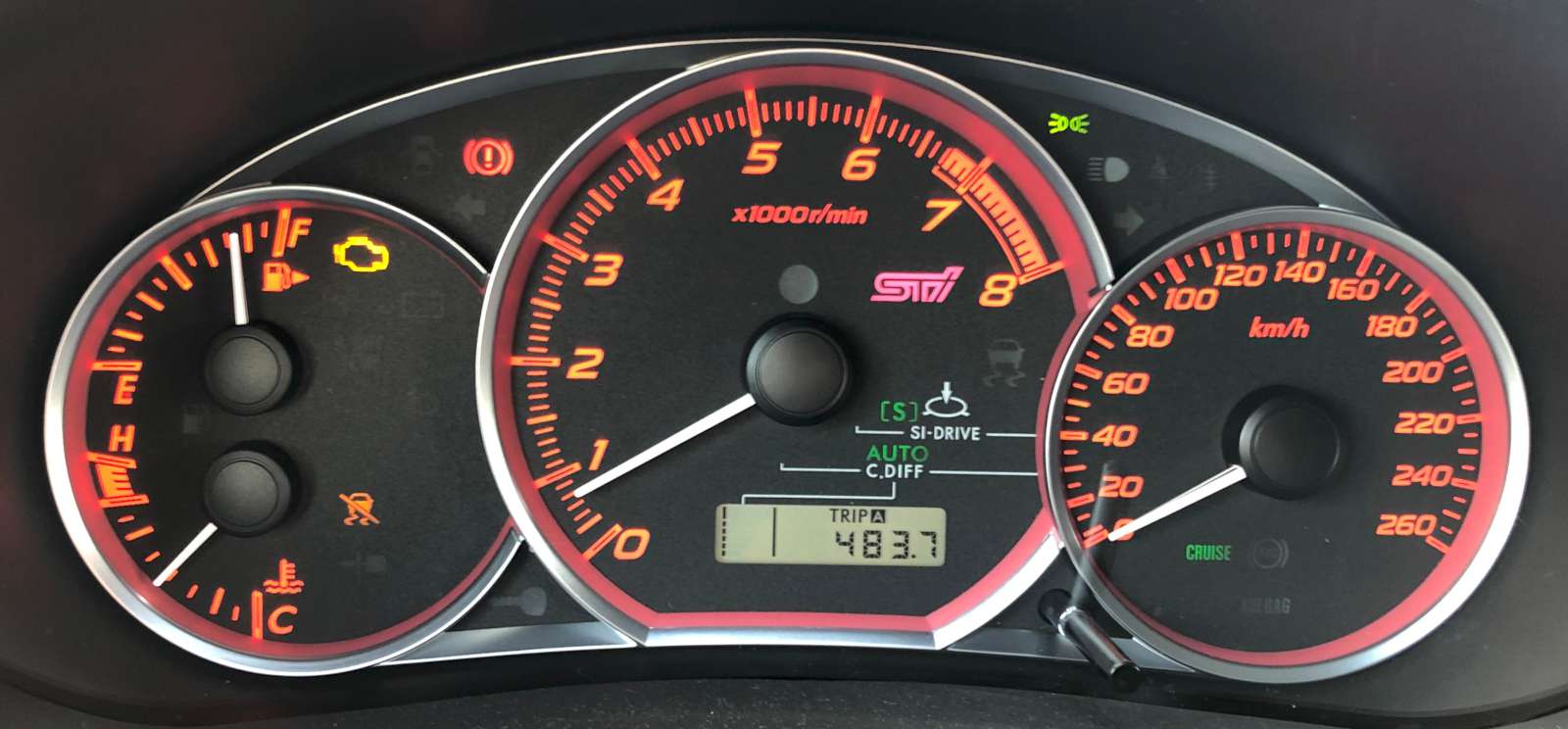
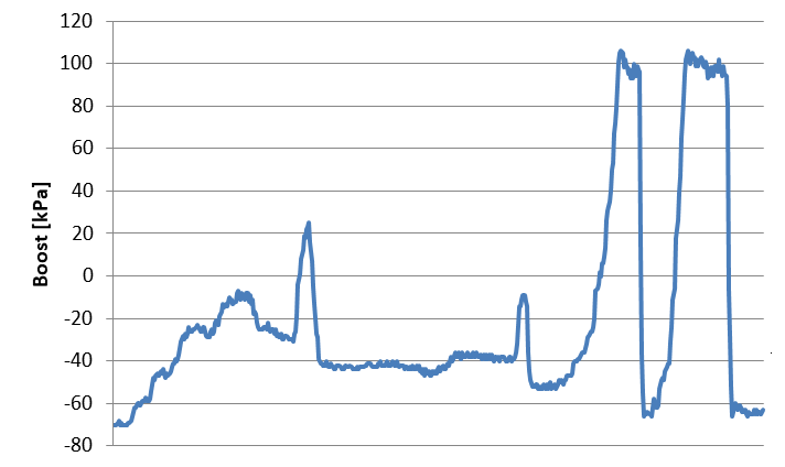
With the factory tune, its stock IHI VF-48 turbo and its EJ257 2.5-liter engine, my STi has a maximum boost of +100 kPa. It overshoots at +110 kPa for a fraction of a second before the boost control solenoid sets its back to +100 kPa. When coasting, the pressure goes down to about –70 kPa and when idling to around –60 kPa. Releasing the throttle, even a little, makes the boost immediately drop. Blipping the throttle in neutral or with the clutch engaged doesn't build any boost, only when hitting the red line (rev limiter) some boost appears, but only 20 kPa or so.
When coasting the intake manifold has about –70 kPa
(vacuum) displayed by seven blue LEDs (left).
When accelerating hard the pressure rises to about +100 kPa displayed
by ten red LEDs (right). (click to enlarge).
The STi comes with three pre-programmed maps in the ECU that give a different throttle response and a different engine power. Subaru calls this "SI-drive" and the three maps are called "I" for intelligent, "S" for sport and "S#" for sport sharp. The first one gives a lot less power and is supposed to save fuel. The two others feel about the same power but the latter being more aggressive and nervous.
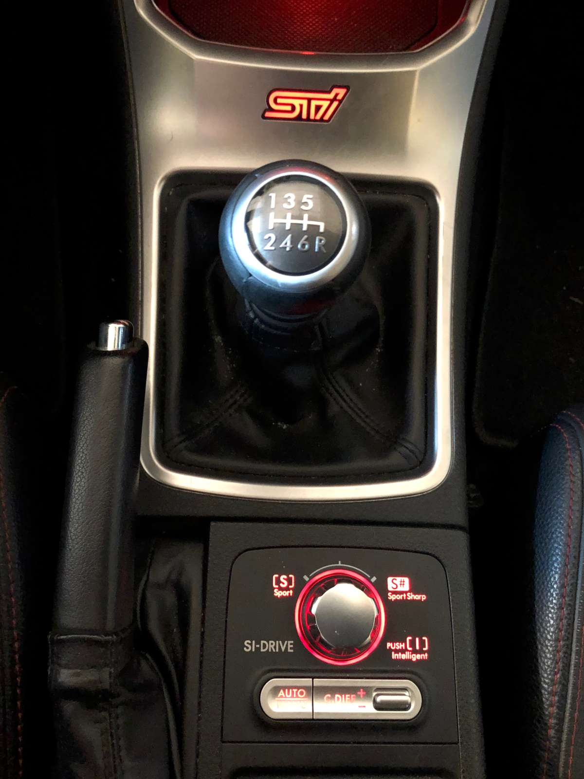
The SI-drive control knob right behind the shifter stick.
(click to enlarge).
It's interesting to play with the SI-drive control and observe the pressure. Both "S" and "S#" modes provide the same 100 kPa boost pressure, but in "S#" mode the pressure rises faster. This with any gear and at any speed, but the engine needs to rev at about 3'000 rpm or more for having the full boost.
50 seconds in a twisty road (in "S#" mode.
In "I" mode, thing are a bit different: in first gear the pressure never rises more than 35 kPa, and 50 kPa in second gear. Starting from third gear, boost increases as the speed of the car increases. From roughly 100 km/h on, the full 100 kPa boost is available. But in "I" mode, boost increases quite slowly. But frankly speaking, "I" mode is kind of useless for this type of car.
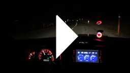
Watch a short movie showing the gauge in action:
gauge-in-action.mp4
(965,869 bytes, 23 s, H264,
640 × 360, 29.97 fps).
It's funny to drive with this gauge; it's pleasant to see all these red LEDs while feeling the push of the engine. Not a must-have tool, far from that, but a nice little toy that gives useful information on what and how the engine is doing. I find the factory turbo to be "too silent" and it's a pity you don't hear the turbine whistling as it spools up as in some tuned cars. So, this gauge visualizes what the turbo is doing and provides a similar feedback. I hope you'll find this page useful and maybe of some help, should you decide to build your own gauge. In any case, I wish you plenty of fun with your turbo and I hope it will deliver plenty of boost to your engine for a long time. Always stay safe and don't drive like a fool: the road is not a racing track.
The STi is a wonderful car to drive, it's really funny.
But if you like speeding, don't be a fool: do it on a racetrack.
(click to enlarge).
| Home | Mechanics | Page hits: 016016 | Created: 02.2021 | Last update: 04.2021 |