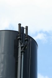

One day, while taking and old steam boat on a lake, I saw a nice steam whistle installed on top of the main stack. One has to say that steam whistles rarely go unnoticed. A nice black-painted chime whistle composed by two simple organ-pipe resonators that make such a typical sound in a cloud of steam (pictures below). Wow, I said, I want to build one of those, just for fun.
The next day I built a prototype with PVC pipe and some corks based on the same principle of the organ flue pipes; there are some minor differences with whistles, like the shape of the mouth of the mounting of the resonator, but the principle is the same and was good enough for me.
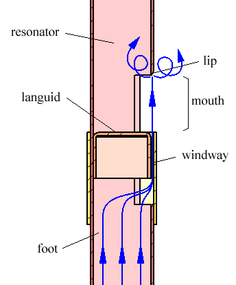
The figure above shows how it works: the gas (steam or air) entering the foot is forced though the windway where it accelerates due to the small cross-section. The jet of gas crosses the mouth and impinges on the lip where turbulence occurs. This turbulence excites the column of gas in the resonator and makes it oscillate.
Since it was actually quite easy to get the PVC whistle to work, I decided to go for a metal version. Copper tubing is easy to find in general hardware stores, can be easily soldered, has a nice color and don't get rusted.
Instead of steam I decided to use compressed air which is easier to find at home. But this whistle will work fine also with steam, if you are lucky enough to have a boiler. Just keep in mind that steam has a lower density than air and will produce a higher pitch.
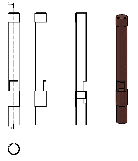
A straight 22 mm (outer diameter) copper pipe makes the foot and the resonator divided by a cap playing the role of the languid. Regular plumbing copper tube has a wall thickness of 1 mm and an internal diameter of 20 mm. An 18 mm tube cap has an inner diameter of 18 mm and an outer diameter of 20 mm and works perfectly for the languid. I just had to slightly adjust its outer diameter by rubbing with sandpaper to make it slide inside the 22 mm pipe.
The mouth and the windway are cut in the main pipe. Just a rectangular hole about 20 mm wide and 45 mm high does the job. The lip is filed to an angle of about 30°. The languid is pushed inside the pipe and positioned about 20 mm below the lip and soldered leaving a mouth opening of about 20 × 20 mm2. Keep in mind that tin-lead solder has a melting point of about 180°C: this is fine for compressed air and regular steam, but for superheated steam (more than 100°C) you should consider silver brazing instead of soldering.
To create the windway, a 22 mm junction is fitted around the main pipe. These junctions have an inner diameter of 22 mm and fit perfectly on the pipe but usually have a small punch in the middle that needs to be filed off. Position the junction aligned to the languid: it should cover the rest of the rectangular hole cut in the main pipe. Solder it in this position but be careful and use as little solder as possible since there is a risk of clogging the windway.
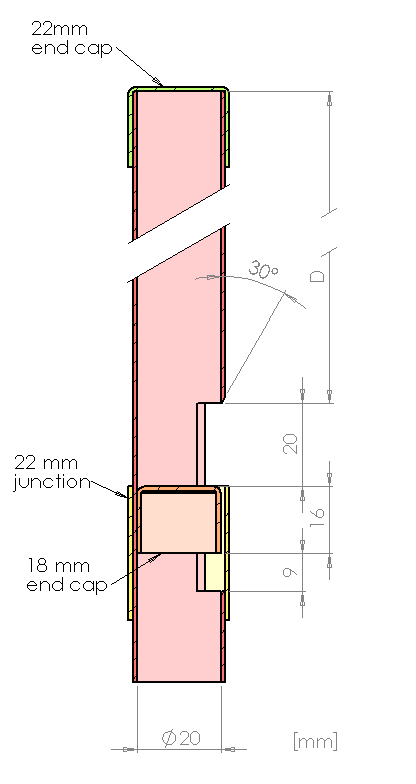
Dimensions are not critical: higher mouth requires more pressure; a wider mouth makes a louder sound but requires a higher flow. The dimensions of the foot have no influence on the whistle. The length of the resonator gives the pitch and can somehow be adjusted by sliding the top cap before soldering it into place. Of course, the whistle will also work with a top end open, but closing it will produce a much lower frequency saving space and copper. Tuning the whistle is not easy: the pitch depends a lot on the pressure and the note is not clean a as sine wave. With the cap on, a resonator length D of 210 mm will produce a note at about 400 Hz when running on compressed air.
A chime whistle is a whistle composed by two or more resonators playing a chord. The simplest chord is composed by two notes with a 3/2 frequency ratio and this was the choice for my whistle. Two simple whistles as described above were constructed, one with a resonator length D of 210 mm and the other one with a resonator of only 140 mm (3/2 ratio, frequency around 600 Hz). The same pipe diameter was used to keep things simple. Their feet were connected together with a T-junction and fed through a control valve built from hardware store parts. The figure below shows how the whistle looks like.
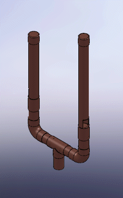
Usually one should tune the resonators so that the frequency ratio is exactly 3/2 but I found this operation quite difficult because the pitch depends on many factors, and primarily on the pressure of the gas. I finally soldered the cap of the second resonator in the position it produce the nicest sound to my ear, without being sure if this corresponds to the right tuning.
In order to make the whistle work, a minimum pressure is required. Below this pressure the air will go through the windway without producing any sound (except the noise of the flowing air). Above this threshold, increasing the pressure will increase the sound level and will also slightly increase the pitch. But there is a maximum pressure that, when exceeded, will make the fundamental frequency disappear and the pitch jump to a much higher frequency. The whistle is said to be over-blown.
The whistle described here has a minimum working pressure around 0.5 bar and overblows at about 6.5 bars. It uses about 2 l/s of air at 6 bars and produces a sound level of 116 dBA at a distance of 1 m.
Listen to this chime whistle: chimewhistle.wav (1,981,348 bytes).
I showed my homebrew chime steam whistle to a friend of mine who works for the Swiss railways and is a real train enthusiast: he was very interested told me he should have a real one somewhere. He came back a few weeks later with the one showed in the picture below.
It's a compressed air whistle mounted on electric locomotives. It's made with brass: casted, machined and than polished. It's about 20 cm high and weight about 2.7 kg: a really nice piece. It can disassembled in four parts as shown in the pictures below.
The windway is circular and the mouth occupies the whole circumference. The resonator is short and wide, is ball shaped and is held in place by a rod in its axis as usual in many many whistles. According to my friend, the pressure of the compressed air supply on these kind of locomotive is something around 8 to 10 bars, but when connected to a small compressor we couldn't make it work at the first try. All we got was just the beginning of a very weak whistle followed by the noise of the escaping air. The problem with these devices is that they require a very high airflow. The diameter of the feed pipe (3/4") gives an idea of what kind of air supply was installed on the locomotive. When fed with a small hobby compressor which as a small diameter output connection, as soon the air start to flow the pressure drops and the sound vanishes. In order to make it work, it was necessary to install a large diameter ball-valve directly on the tank. 1/2" was the maximum we could fit. With this we could make it whistle, but the 24 liters of air at 8 bar are just enough for a half a second tone... The measured sound level was 120 dB(A) at 1 m distance.
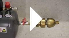
Watch the movie: steamwhistle.mp4
(515,205 bytes, 12 s, H264, 640 x 360, 24 fps).
| Home | Mechanics | Page hits: 090622 | Created: 12.2012 | Last update: 12.2012 |