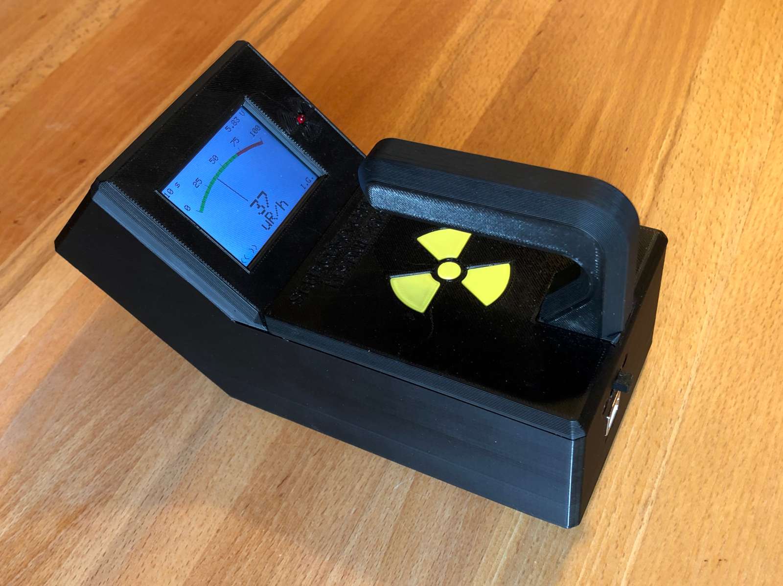
The finished SI-8B pancake Geiger counter. (click to enlarge)
Does a man with four Geiger counters need another one? No, of course not,... oh, well, maybe,... actually yes, thinking again, he sure does. Especially if he doesn't have a pancake detector but has a pancake tube laying around in his junk-box since years... So, it was time to bring that old tube back to life and this project got started.
The finished SI-8B pancake Geiger counter. (click to enlarge)
Most Geiger tubes are in the shape of... a tube: that is a pipe, a long thin and tall cylinder. Radiation enters from the long round face that is commonly made of very thin metal (but glass tubes exist as well). These tubes are easy to construct but offer a relatively low surface for the radiation to enter and be detected. Especially when measuring a small source, even very close to the tube, a lot of the radiation will simply miss it and go undetected. This is why pancake tubes are for: they are mostly cylindrical as well, but are wide and short, more like a disc. Radiation enters form one of the flat sides that is commonly made out of a thin metal or mica foil. Because of this large and flat window, pancake tubes are very good at colleting rays from small sources and are suitable for detecting low radiation levels. There is only one downside: this flat surface is extremely delicate and easily breaks, especially if it's made of mica. Mica is as fragile as glass and is much thinner than a sheet of paper. Touching it is enough for scrapping the tube... be very careful, especially when measuring very close to a source.
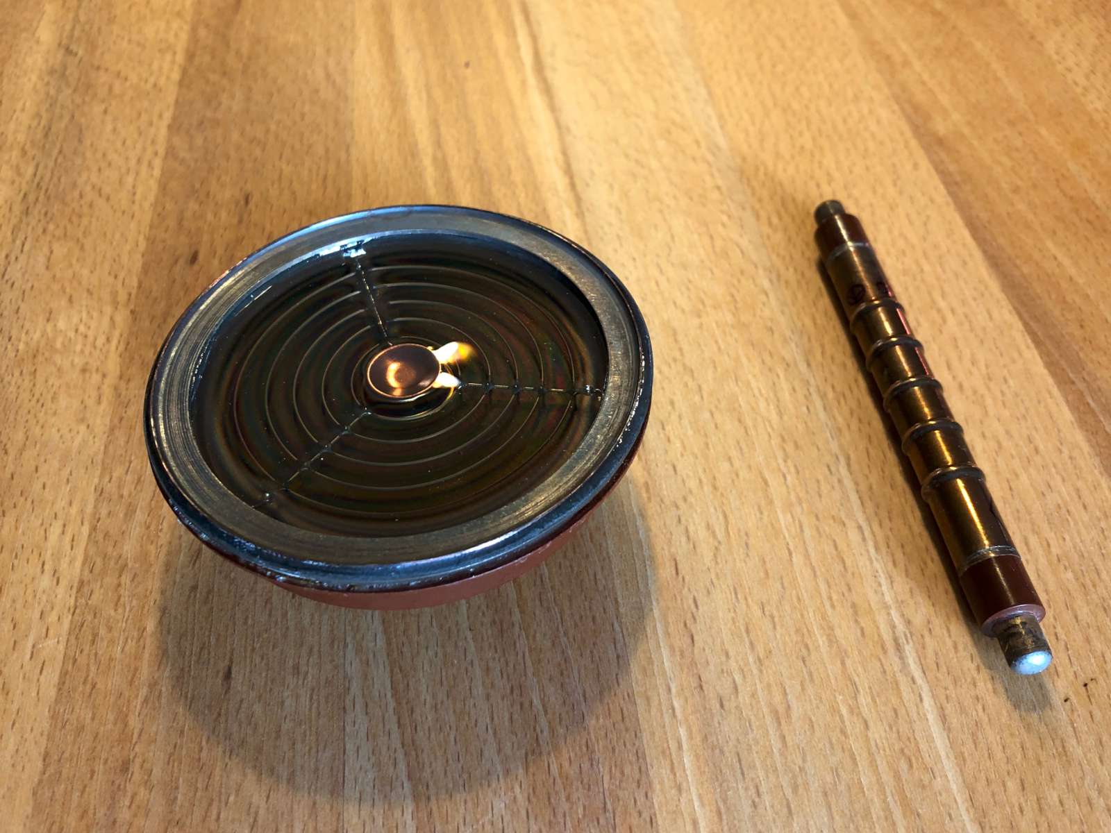
On the left the SI-8B (СИ-8Б) pancake Geiger tube
used in this project next to a classical long and thin SBM-20
(СБМ-20) tube on the right for comparison.
(click to enlarge)
The tube used here is a SI-8B (СИ-8Б) that has the following characteristics:
| Minimum operating voltage | 360 V |
| Maximum operating voltage | 440 V |
| Maximum plateau slope | 0.4 %/V |
| Maximum voltage-current slope | 1.5 %/V |
| Maximum counting speed | 3'400 cps |
| Maximum operating current | 18.2 μA |
| Maximum exposure (within 1 minute) | 300 R/h |
| Radiation type | Soft beta |
| Nominal operating voltage | 390 V |
| Minimum voltage pulse amplitude | 20 V |
| Dead time | 160 μs |
| Inter-electrode capacitance | 13 pF |
| Sensitivity to 60Co | 350...550 cps/(μR/s) |
| Current sensitivity (at 5 μR/s dose) | 8...15 μA |
| Maximum own background | 2.0 cps |
| Efficiency to beta radiation | 50...85 % |
| Minimum life expectancy | 1·1010 counts |
| Operating temperature range | –50...+60 °C |
| Mica window area | 30 cm2 |
| Maximum diameter | 80 mm |
| Maximum length | 33 mm |
| Maximum weight | 100 g |
These tubes are easy to find on the import market for quite a reasonable price. I don't know if this will still be the case when you'll be reading this page, but this was true in 2016 when I actually bought it.
This circuit is very similar to the one I designed for my twin tube counter, so I won't be describing again here the same thing, I'll just point out what is different.
The high voltage converter used to power the tube is almost the same circuit, based on a disposable camera flash transformer. Only the voltage stabilization network has been modified and uses a string of Zener diode to generate 390 V. A 4.7 Ω series resistor (R2) with the supply rail filters the noise generated by oscillator and a capacitor (C5) has been added in parallel with the switching transistor (T1) to "round off" the signal and generate less noise. It oscillates at about 9 kHz.
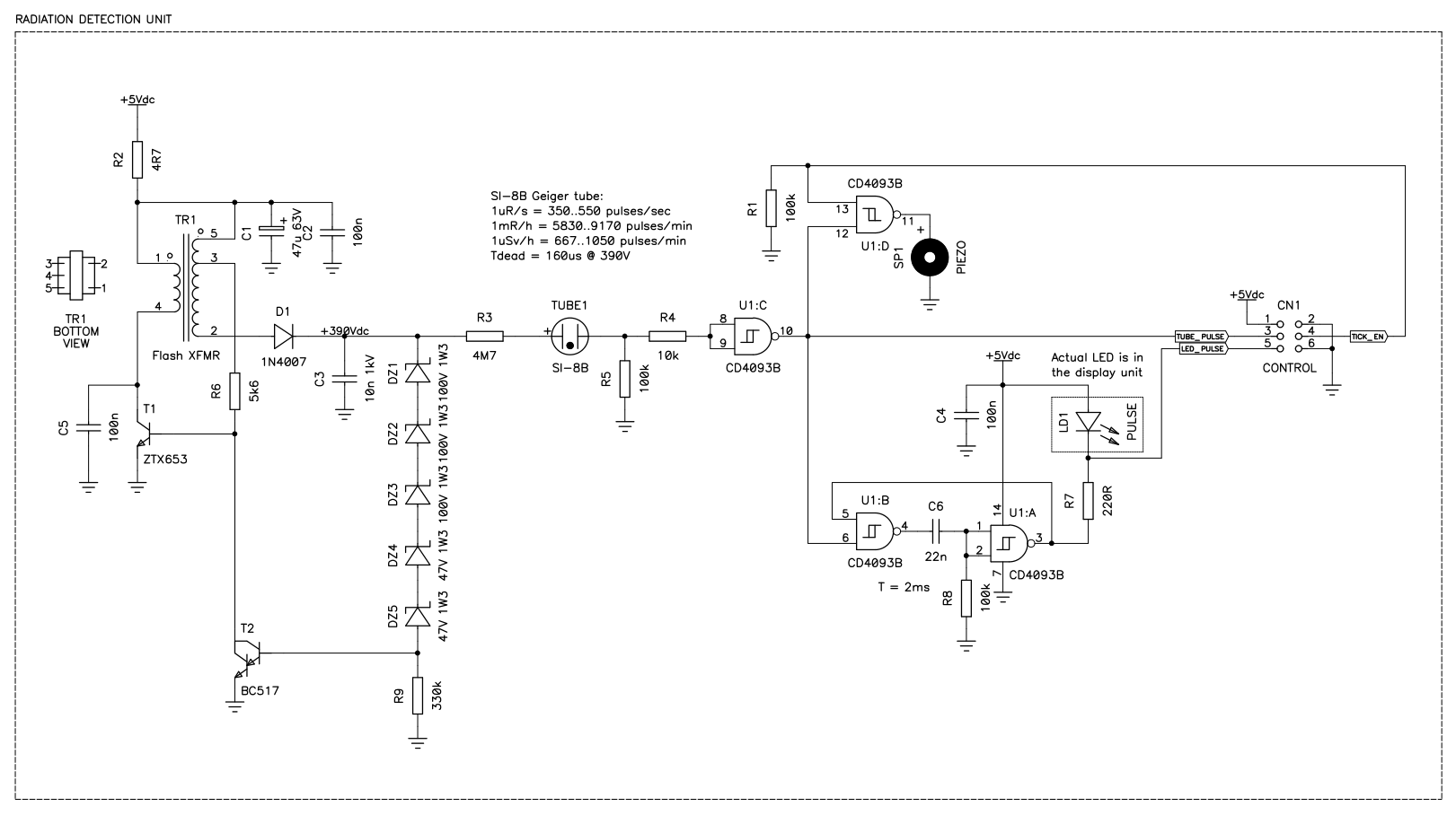
Circuit diagram of the radiation detection unit with the high voltage
power supply and the pulse amplifier. (click to enlarge)
The tube is fed via a 4.7 MΩ resistor (R3) and pluses are detected across a 100 kΩ shunt resistor (R5). The pulse detection and shaping circuit is very similar to the one used in the LX1407 counter, the only difference is that pin 13 of U1:D is used here to control the ticking sound on or off. When this pin is low, the output is forced high and no sound is emitted. Because here we use a piezo speaker, it doesn't matter if the output of U1:D idles high or low: a piezo is like a capacitor and doesn't draw any current if fed with a DC voltage. If we used a dynamic speaker instead (one with a coil and a magnet, so to speak) this wouldn't work and a different circuit would be needed. R1 is there to force pin 13 of U1:D to a known state (low in this case) while the microcontroller is booting up until it configures its D4 pin as an output and takes control of this function.
Pulses from the tube are sent to the microcontroller pin D2 and generate interrupt INT0 on every falling edge. The only major difference from the previous counters is the use of a 2.4" graphical display based on an ILI9431V TFT controller and a XPT2046 resistive touch screen controller. These displays are relatively cheap and are quite good looking on the finished product. The only downside is that they are slow to control via the SPI interface and that a lot of microcontroller memory is needed for the graphical routines. These displays come with an on-board SD-card holder that is not used in this project, although it has been connected to the microcontroller, just in case.
Because the display, the touch screen controller and the SD-card work with a 3.3 V power supply while the Arduino runs at 5 V, seven 2.2 kΩ - 3.9 kΩ voltage dividers are necessary to properly drive these three peripherals. Furthermore the SPI communication is pretty fast (the clock runs at 8 MHz) and it was necessary to use lower values resistors (470 Ω - 820 Ωrespectively) for the dividers of MOSI and CLK that run at high speed. A true level shifter IC would have been a good idea here, but I didn't have one on hand, so I used resistor dividers that also work quite well. The 3.3 V regulator is included in the display module and one doesn't have to bother with it. In its inputs the Arduino readily accepts 3.3 V signals and no voltage translator is necessary.
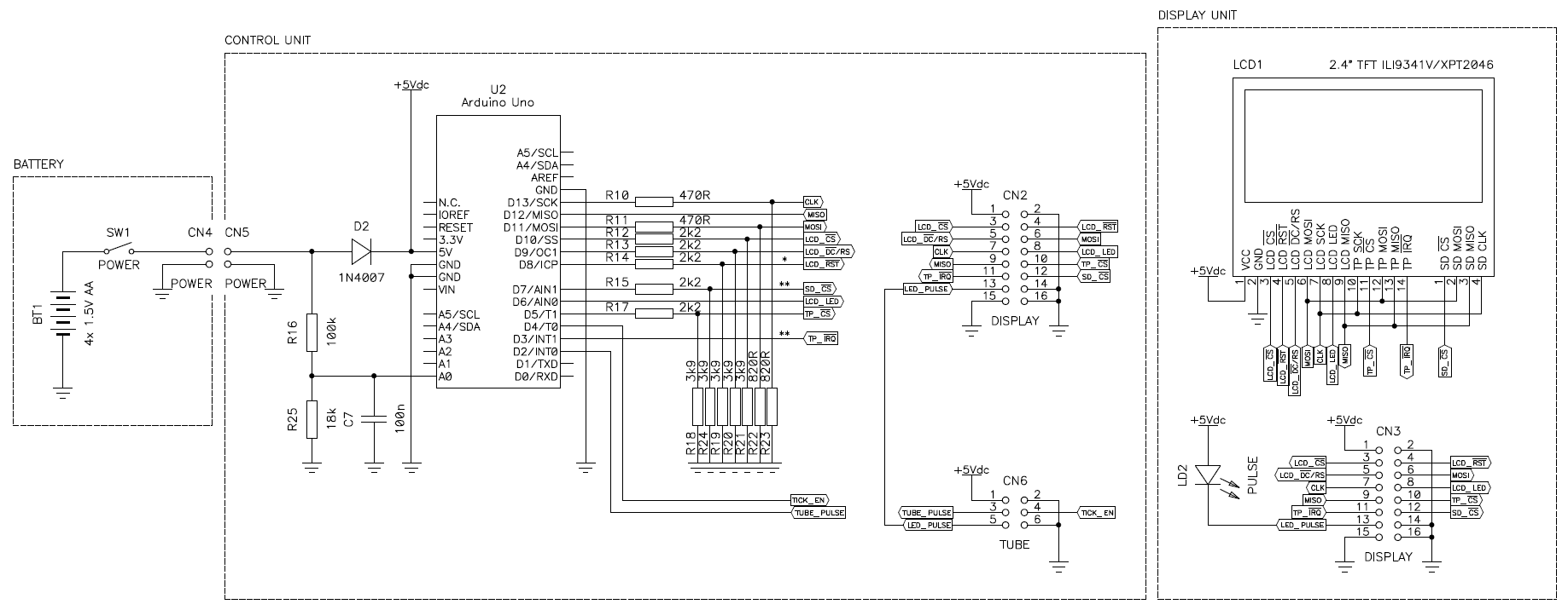
Circuit diagram of the microcontroller unit with the Arduino Uno and
the TFT display. (click to enlarge)
The microcontroller used here is a complete Arduino Uno board. The pancake tube is pretty big, so, there was plenty of space for it. The instrument is powered by four AA alkaline cells through a protection diode that has the double function of lowering the supply voltage from 6 V down to 5.3 V that is more suitable for the ATmega microcontroller on the Arduino. Even if this is slightly out of spec, I have been using this trick for years and never had a problem. A resistive voltage divider composed by R16 and R25 allow measuring the battery voltage with the internal voltage reference of 1.100 V. Of course, the instrument can also be powered with the USB cable.
The full schematic is available here: si-8b.pdf (76,937 bytes).
Probably the biggest difference is in the firmware. In my previous counters, I always counted the pulse for a long period of time and displayed the result at the end. I found that periods of 2, 10 and 60 s work well. The problem is that one has to wait that time before any result is available. Here I tried a different approach: I fixed the integration time to one second and used an array of 60 different counters (actually 61), each one incremented for just one second. So I can now calculate a sliding average on a number those counters, but still have a partial result every second. The integration time can still be set at 2, 10 and 60 seconds, but this only means that 3, 11 or 61 different counters are used to count the pulses, but the display is always updated every second. The firmware always use one counter more than the ones used for averaging so that the average can be calculated without the partial value of the counter currently integrating pulses. So for 60 seconds 61 counters are used, for 10 seconds 11 and for 2 seconds 3. This is very handy as one clearly sees the measured value go up or down when approaching or removing a source without waiting a long time. Of course, for a correct reading, one has still to wait at least that integration time, but with this method one can see it changing and stabilizing.
Because this tube came with a pulse to dose conversion chart, instead of compensating for the dead time and multiplying by one factor, the conversion curve was digitized, split in 13 segments and an interpolation algorithm does the conversion from counts per minutes into microRöntgens per hour. To further convert into nanoSieverts per hour (nSv/h) we use here the same conversion factor as in my other counters, i.e. 1 mR/h is approximately 8.74 μSv/h. More information on unit conversion can be found in my twin tube counter.
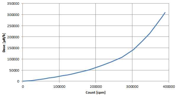
Counts per minute to dose conversion chart, digitized and replotted
from the SI-8B datasheet.
Because of the use of the graphical display, I implemented a nice analog gauge display with green, orange and red zones depending on the intensity of the detected radiation. The scale automatically changes to keep the needle in a reasonable position. Based on what many commercial counters do, I decided to display doses below 600 nSv/h in green, then in yellow until 2'000 nSv/h, and higher values in red. These thresholds are about equivalent to 70 and 250 μR/h respectively, and to 500 cpm (480 cpm) and 1'500 cpm (1'570 cpm).
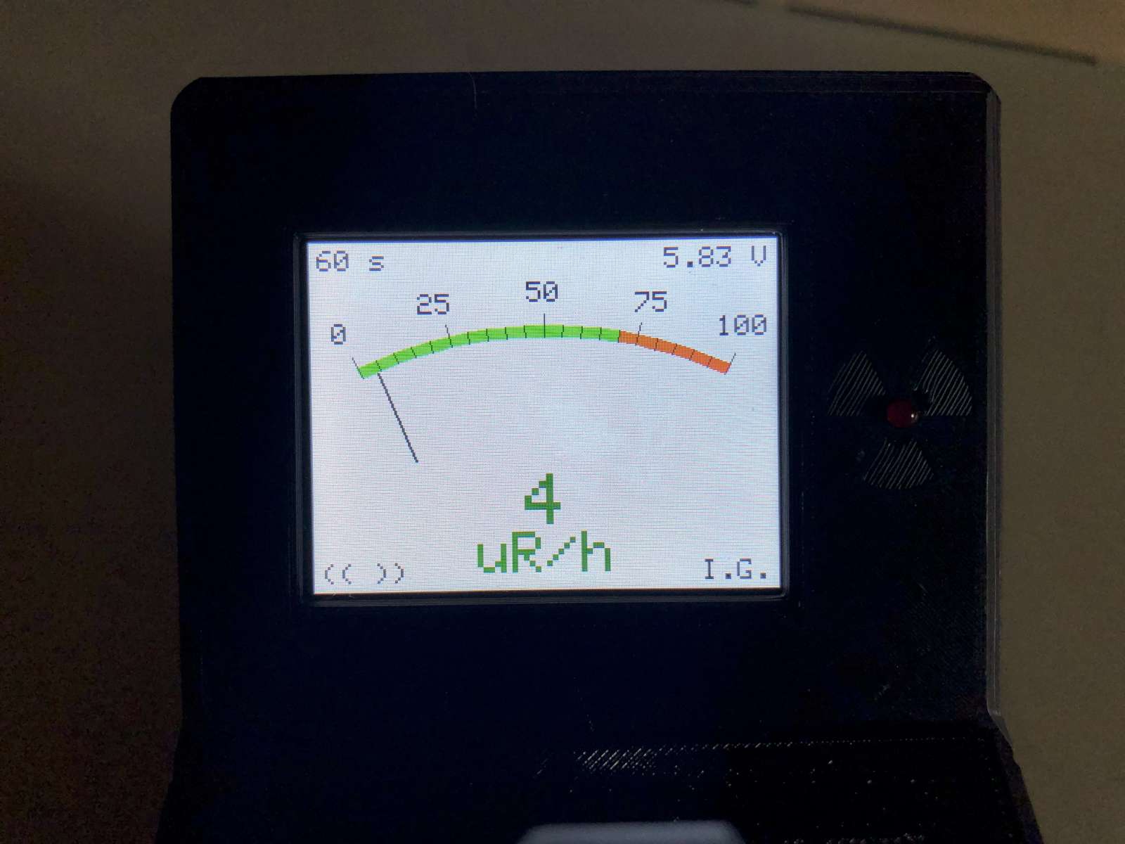
Results are displayed on both an analog gauge and a digital display;
green, orange and red colors indicate how strong the dose is.
(click to enlarge)
Because of the touchscreen, no buttons or switches are required (except the main power switch). By touching the integration time one can cycle it between 2, 10 and 60 seconds. By touching the unit one can cycle it between cpm, μR/h and nSv/h. By touching the sound symbol one can activate the ticking sound on or off, and by touching the battery voltage one can dim the display. Settings are always saved in the EEPROM.
The firmware is available here: si-8b_firmware.zip (564,981 bytes).
The first problem to address is how to mount and connect the tube. It has four Ø2.4 mm pins arranged on a Ø21 mm circle. Because the original socket was more expensive than the tube itself, I had to find another solution. I ended up using four small laboratory Ø2.6 mm female banana connectors that fit almost right. The tube has four solid male pins and is intended to mate with spring loaded female sockets. The banana plugs are the other way around: the male pins are springy and the female sockets are solid tubes. So I cut a slot in the female banana sockets with a small hacksaw and bent them a tiny bit. This closed the gap between the Ø2.4 mm pins and the larger Ø2.6 mm sockets and made them springy enough to ensure a good contact. I soldered them around a Ø21 mm circle on a piece of bare PCB, I drilled a Ø12.5 mm center hole and filed a notch to ensure the tube can only be mounted in the correct way.
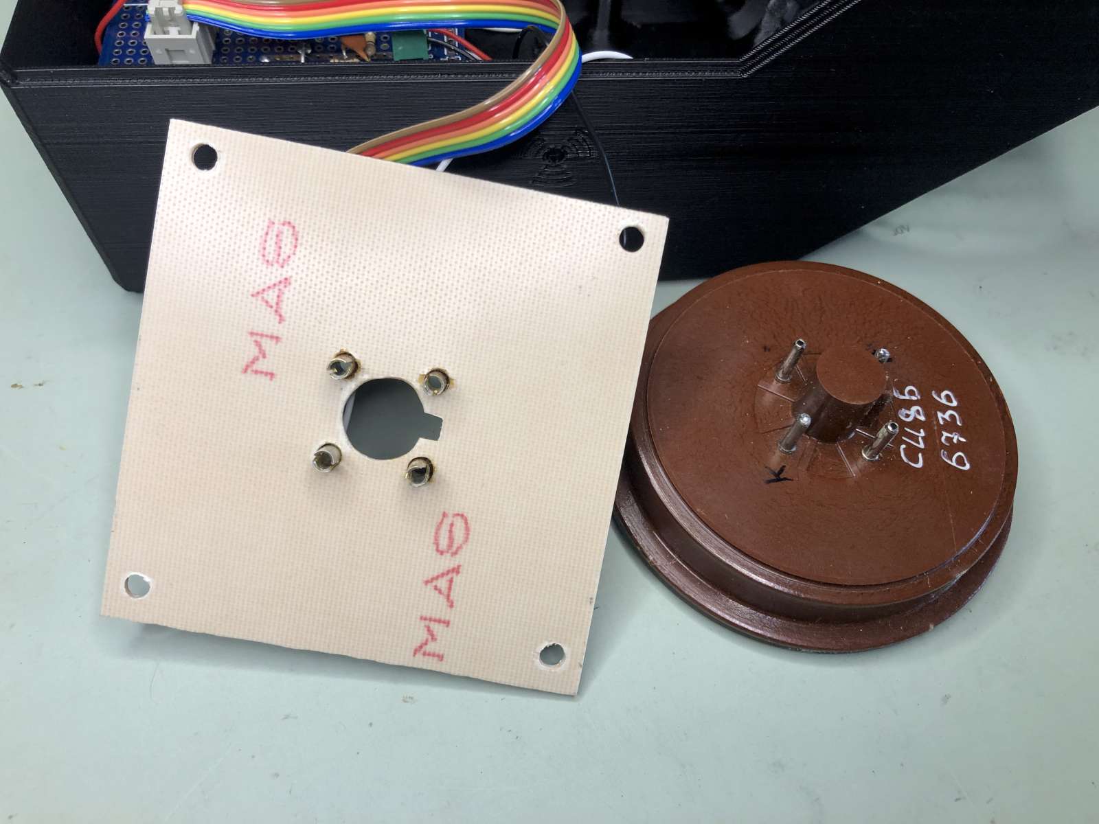
The completed tube socket with the four modified Ø2.6 mm
banana female connectors. (click to enlarge)
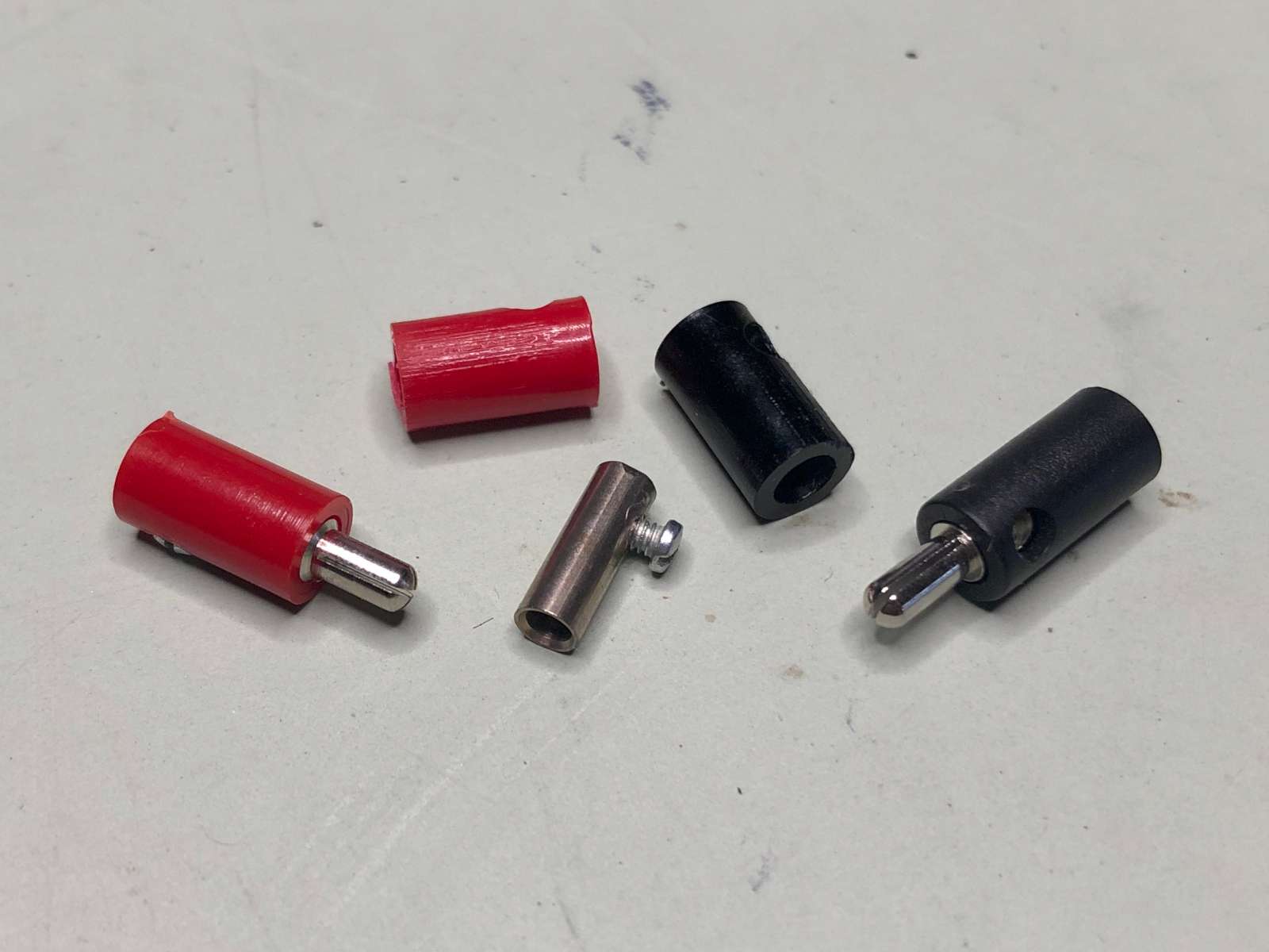
Some 2.6 mm banana plugs and sockets used to connect to the
SI-8B tube. (click to enlarge)
Now I could build the DC-DC converter and the pulse amplifier on this board. Because I wanted to build only one counter, I didn't bother designing a true PCB with traces and holes; I just installed all components "dead-bug" style and got it working in no time at all.
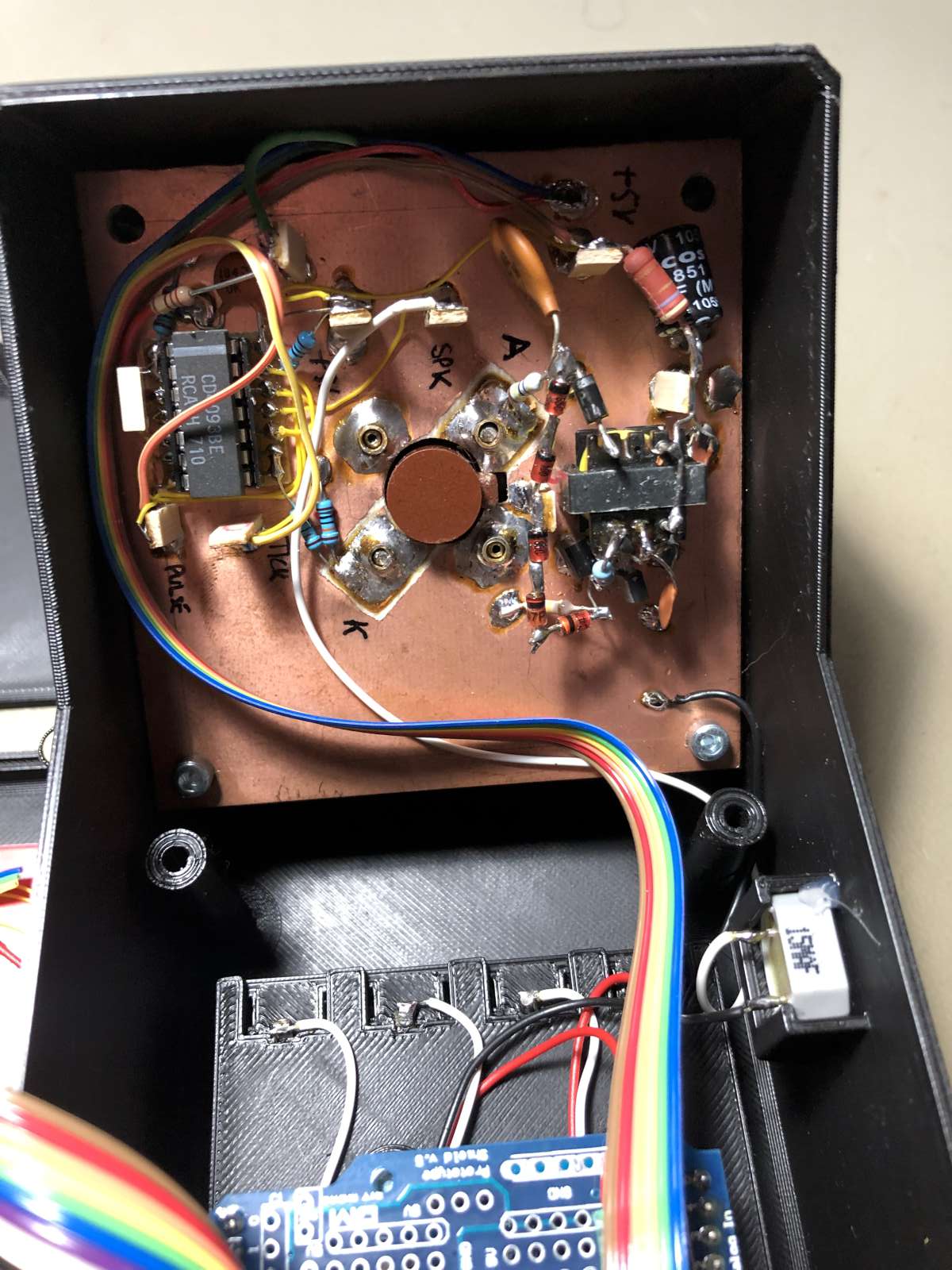
Completed radiation detection unit on the back of the tube socket.
(click to enlarge)
The tube is big and the most difficult part is finding a suitable box to fit all the parts. The original idea was to build a sheet-metal enclosure, but because I wanted the tube mounted at an angle, this was quite complicated to do. So the laziness finally won and I ended up in 3D-printing a plastic enclosure. There is not much to say about it, it's just a simple plastic box. I uses M3 brass inserts for the screws as threads in plastic are too easy to damage. I also 3D-printed a battery compartment, but this turned out to be quite tricky to get right... next time I'll buy a readily made battery holder: a lot less problems to fix for a very cheap price...
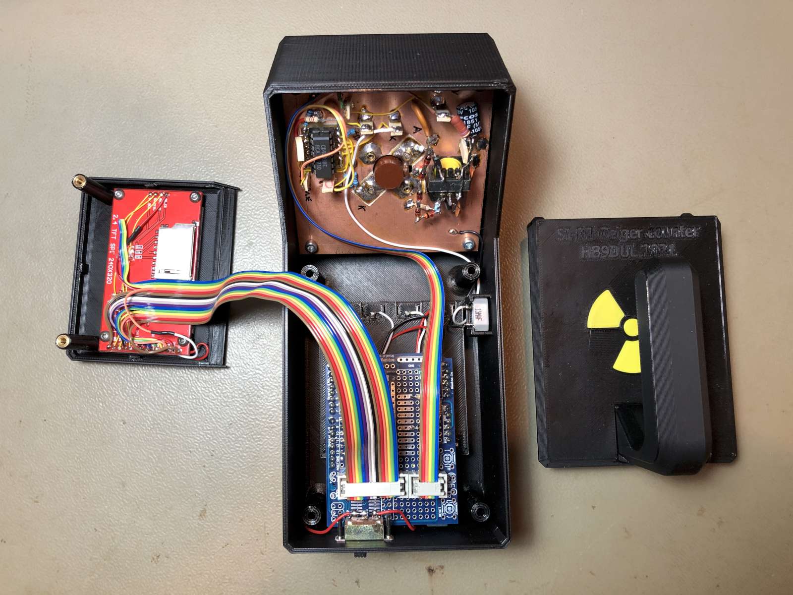
Internal view of the complete SI-8B pancake Geiger counter.
(click to enlarge)
To protect the tube I also 3D-printed a cover that I hold in place with four Ø6 mm × 2 mm magnets. And because the mica window of the tube is really delicate I also added a plastic grid to further protect it. But it's still a fragile tool and should be handled with care, a lot of care. I'm not sure the tube survives if the instrument is dropped on the floor.
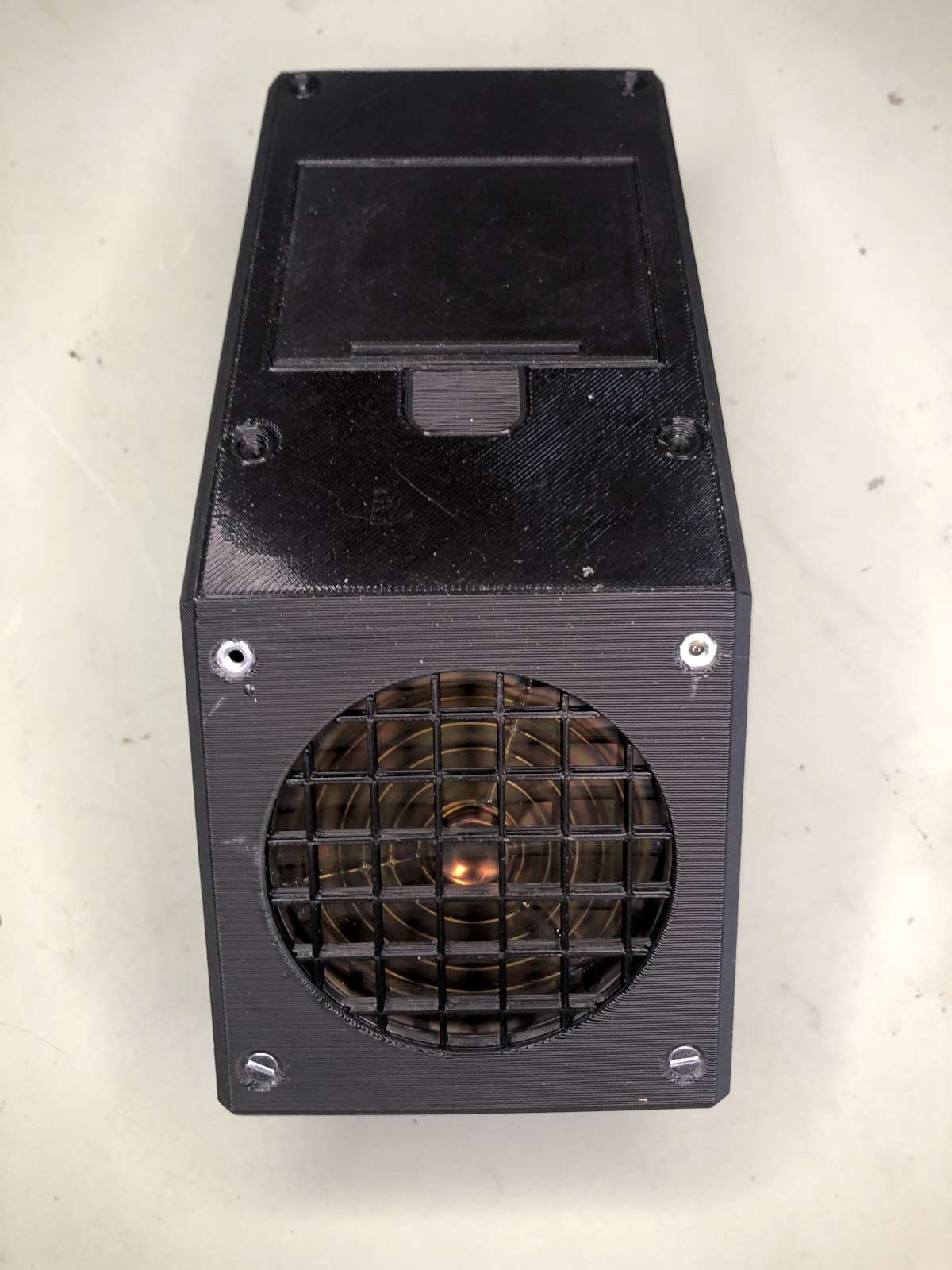
Bottom view of the finished Geiger counter with the protection grid
and the battery compartment. (click to enlarge)
The 3D files (STL) to print the box are available here: si-8b-box.zip (986,443 bytes).
So, here you have it, yet another Geiger counter...
Does it work well?
Yes, sure.
Does it measure right?
Yes, for the little doses I could measure with it, its reading are consistent
with my other counters, and hopefully I never came cross higher doses.
Am I happy with it?
Yes, this large tube is really sensitive to low radiation levels and can pick
up (barely) uranium glass and tritium watches that radiate so weakly that my
other counters could not detect.
Did I really need it?
No, of course not, but it was fun to build and I'm happy to have it.
| Home | Electronics | Page hits: 011167 | Created: 08.2021 | Last update: 11.2022 |